In the circuit shown in figure :
and . Current in circuit is in circuit is and the main current is
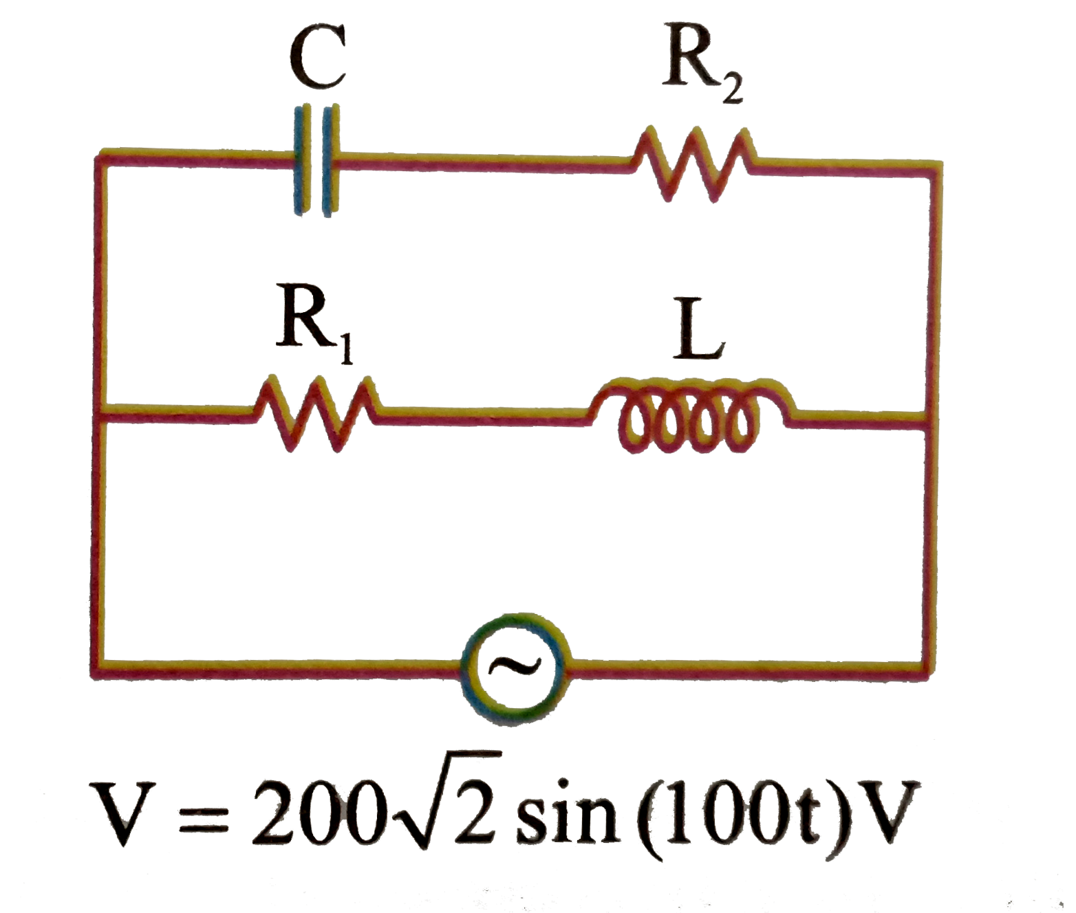
At some instant in the circuit is , then at this instant current will be
The correct Answer is:B
At any time total current
Topper's Solved these Questions
- ALTERNATING CURRENTBook:NARAYNAChapter:ALTERNATING CURRENTExercise:LEVEL - I (H.W)
Explore 23 Videos
- ALTERNATING CURRENTBook:NARAYNAChapter:ALTERNATING CURRENTExercise:LEVEL - II(H.W)
Explore 13 Videos
- ALTERNATING CURRENTBook:NARAYNAChapter:ALTERNATING CURRENTExercise:LEVEL - V
Explore 83 Videos
- ATOMIC PHYSICSBook:NARAYNAChapter:ATOMIC PHYSICSExercise:LEVEL-II (H.W)
Explore 14 Videos
Similar Questions
For a given AC source the average emf during the positive half cycle
View SolutionAn alternating current 'I' is given by I=i0sin2π(t/T+1/4). Then the average current in the first one quarter time period to
View SolutionThe value of current in two series LCR circuits at resonance is same when connected across a sinusodial voltage source. Then:
View SolutionA proton and an alpha-particle enter a magnetic field in a direction perpendicular to it. If the force acting on the proton is twice that acting on the alpha-particle , the ratio of their velocities is
View SolutionIn the circuit shows in Fig E=15V, R1=1Ω, R2=1Ω, R3=2Ω, and L=1.5H. The currents flowing through R1,R2,and R3 are i1,i2, and i3, respectively.
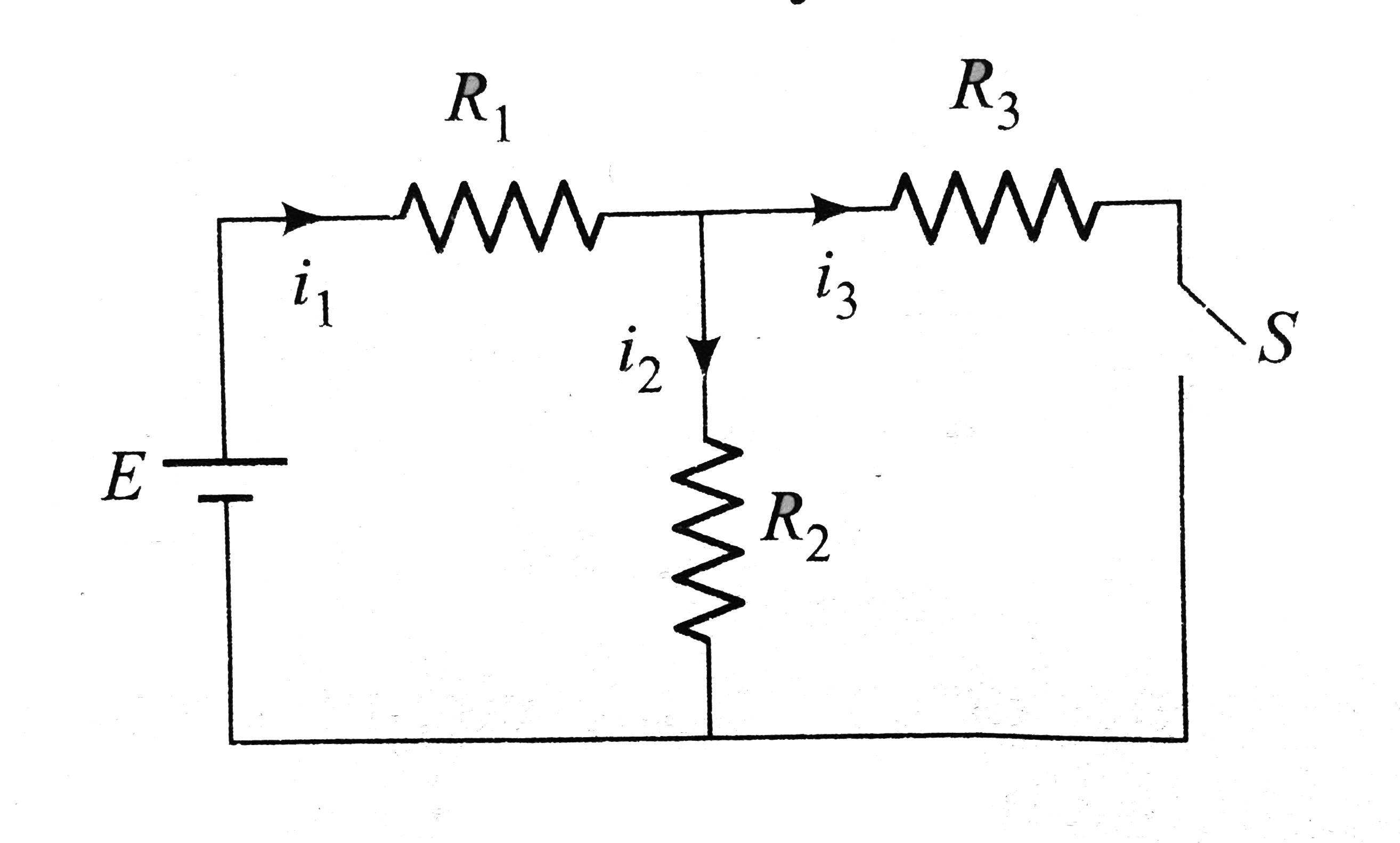
Immediately after tuning switch S on,
View SolutionIn the circuit shows in Fig E=15V, R1=1Ω, R2=1Ω, R3=2Ω, and L=1.5H. The currents flowing through R1,R2,and R3 are i1,i2, and i3, respectively.
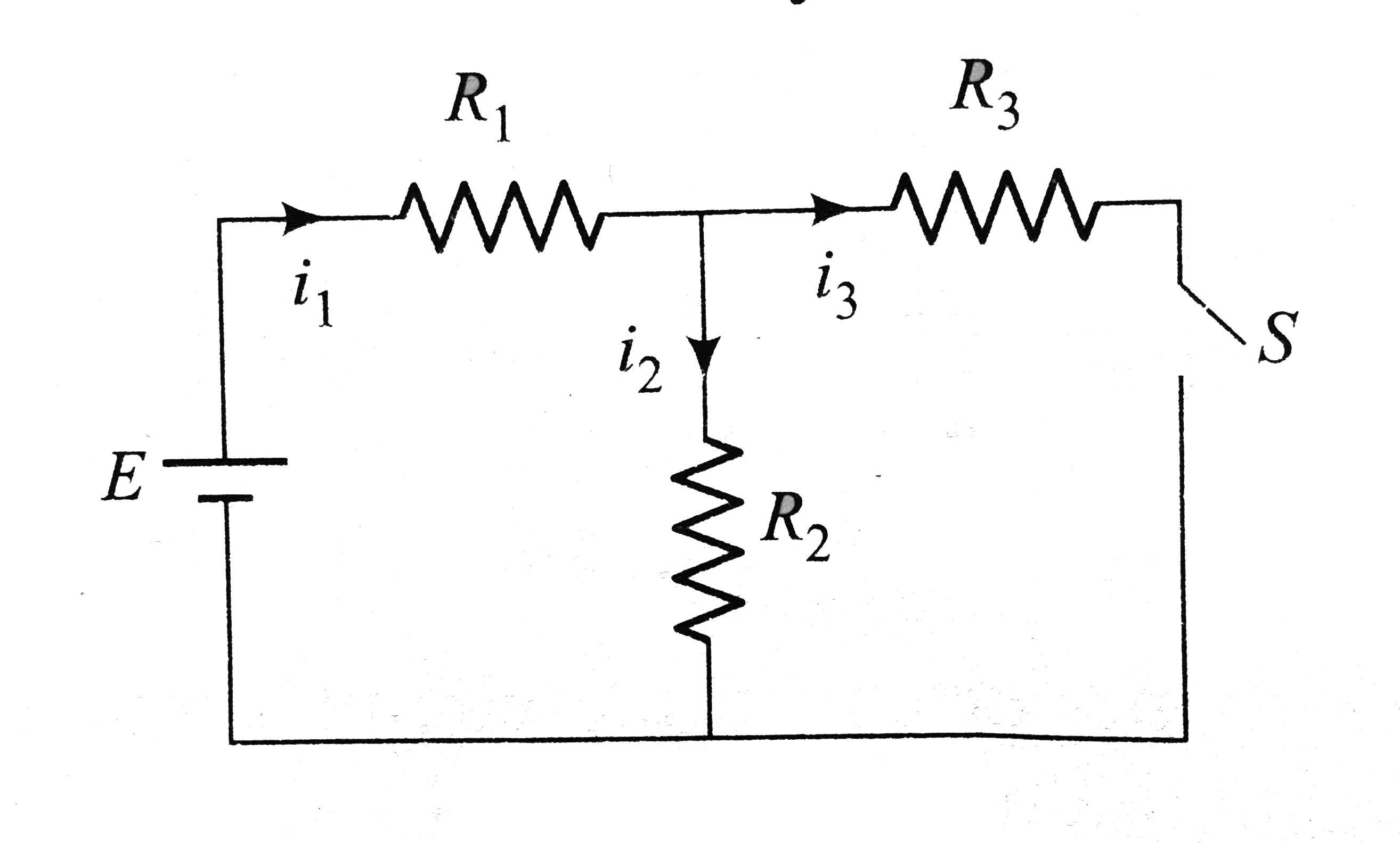
After the circuit reaches the steady state,
View SolutionIn the circuit shows in Fig E=15V, R1=1Ω, R2=1Ω, R3=2Ω, and L=1.5H. The currents flowing through R1,R2,and R3 are i1,i2, and i3, respectively.
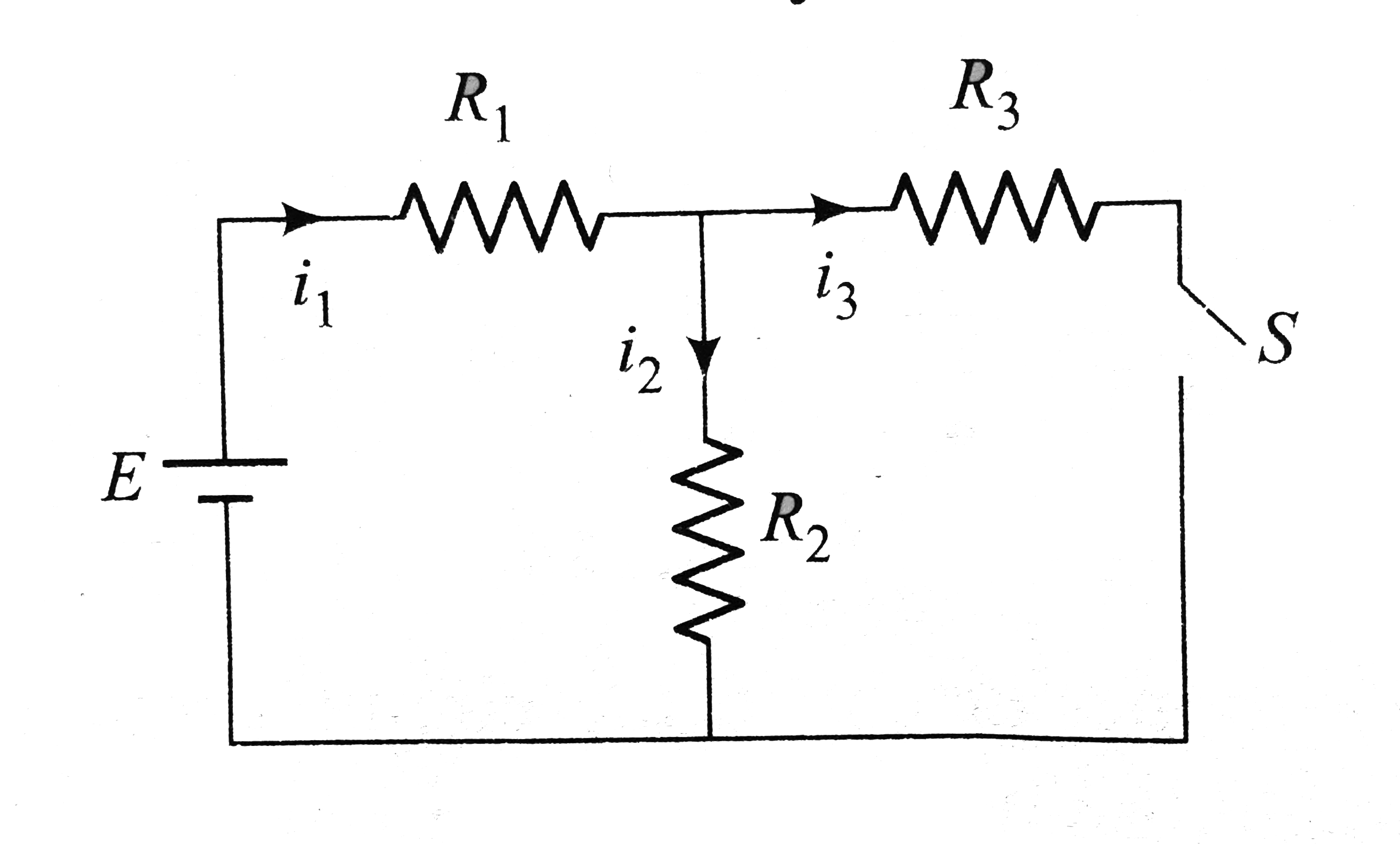
Immediately after connecting switch S,
View SolutionIn the given circuit if I_(1) and I_(2) be the current in resistance R_(1) and R_(2) respectively then:
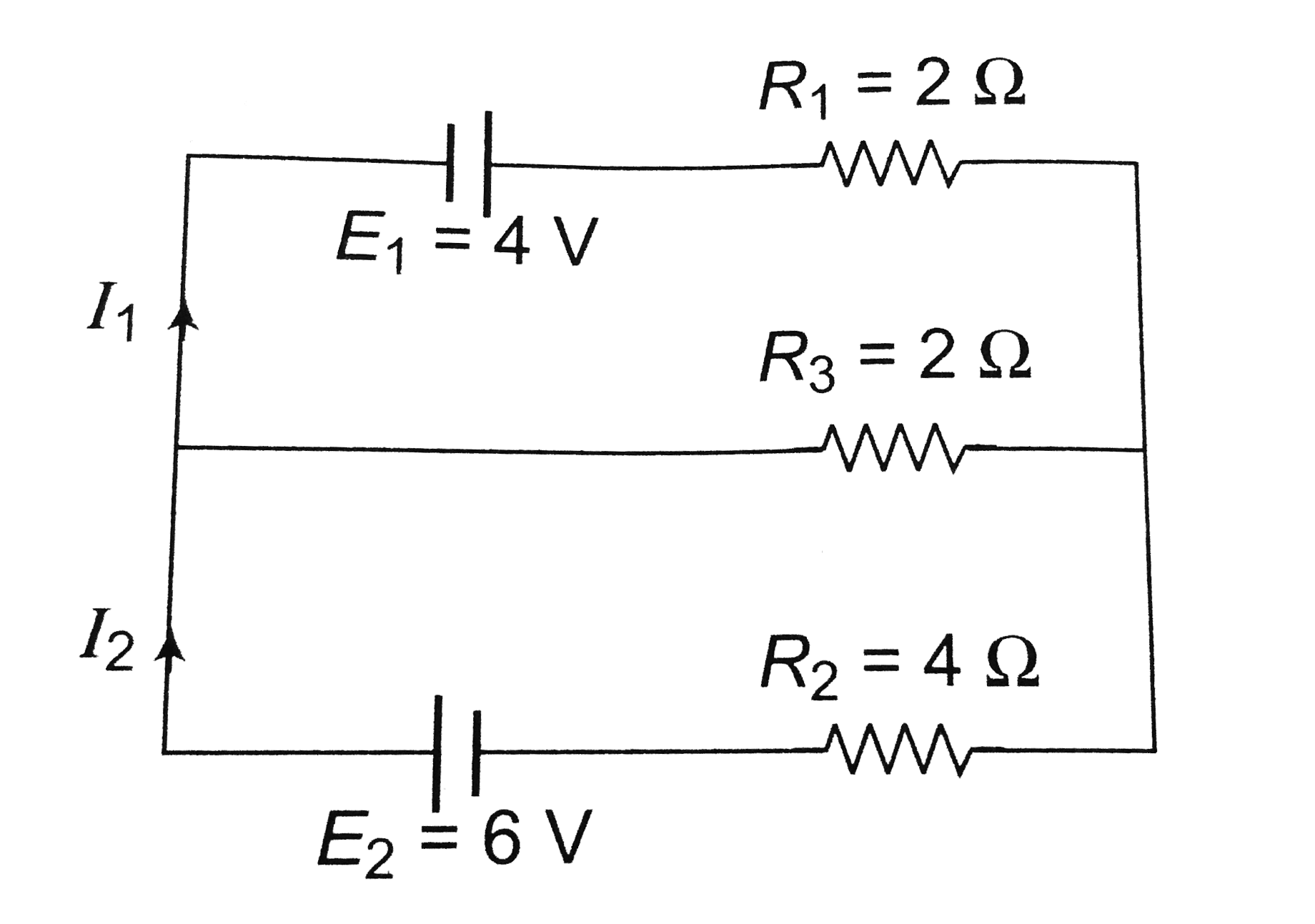
View SolutionIn the circuit shown below E1=4.0V,R1=2Ω,E2=6.0V,R2=4Ω and R3=2Ω. The current I1 is
View SolutionIn the circuit shown in figure : R = 10 Omega , L = (sqrt(3))/(10) H, R_(2) = 20 Omega and C = (sqrt(3))/(2) mF . Current in L - R_(1) circuit is I_(1) in C - R_(1) circuit is I_(2) and the main current is I Phase difference between I_(1) and I_(2) is
View SolutionIn the circuit shown in figure :
R=10Ω,L=√310H,R2=20Ω and C=√32mF. Current in L−R1 circuit is I1 in C−R1 circuit is I2 and the main current is I
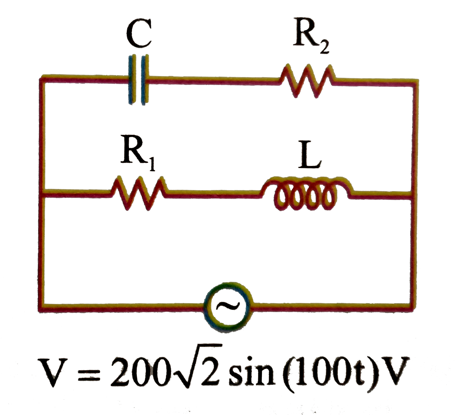
At some instant current in L−R1 circuit is 10A. At the same instant current in C−R2 branch will be
View SolutionFigure shows a circuit with three ideal batteries in it. The circuit elements h ave the following values
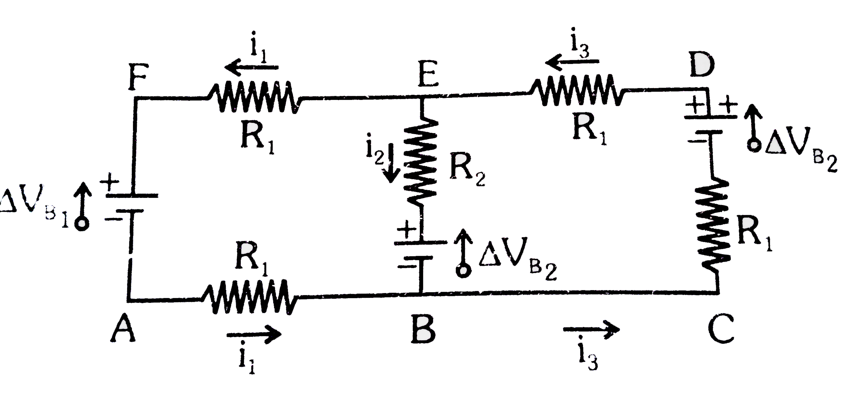
ΔVB1=3.0V,ΔVB2=6.0V
R1=2.0Ω,R2=4.0Ω The currents i1,i2 and i3 as shown in the circuit have the values.
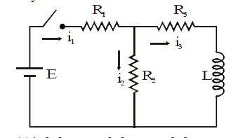
View SolutionIn the circuit shown in adjoining fig E =10V, R1=1ΩR2=2Ω,R3=3ΩandL=2H. Calculate the value of current i1,i2andi3 immidiately after key S is closed :-
View SolutionIn the circuit shown in figure : R = 10 Omega , L = (sqrt(3))/(10) H, R_(2) = 20 Omega and C = (sqrt(3))/(2) mF . Current in L - R_(1) circuit is I_(1) in C - R_(1) circuit is I_(2) and the main current is I Phase difference between I_(1) and I_(2) is
View SolutionIn the circuit shown in figure : R = 10 Omega , L = (sqrt(3))/(10) H, R_(2) = 20 Omega and C = (sqrt(3))/(2) mF . Current in L - R_(1) circuit is I_(1) in C - R_(1) circuit is I_(2) and the main current is I At some instant current in L - R_(1) circuit is 10 A . At the same instant current in C - R_(2) branch will be
View Solution