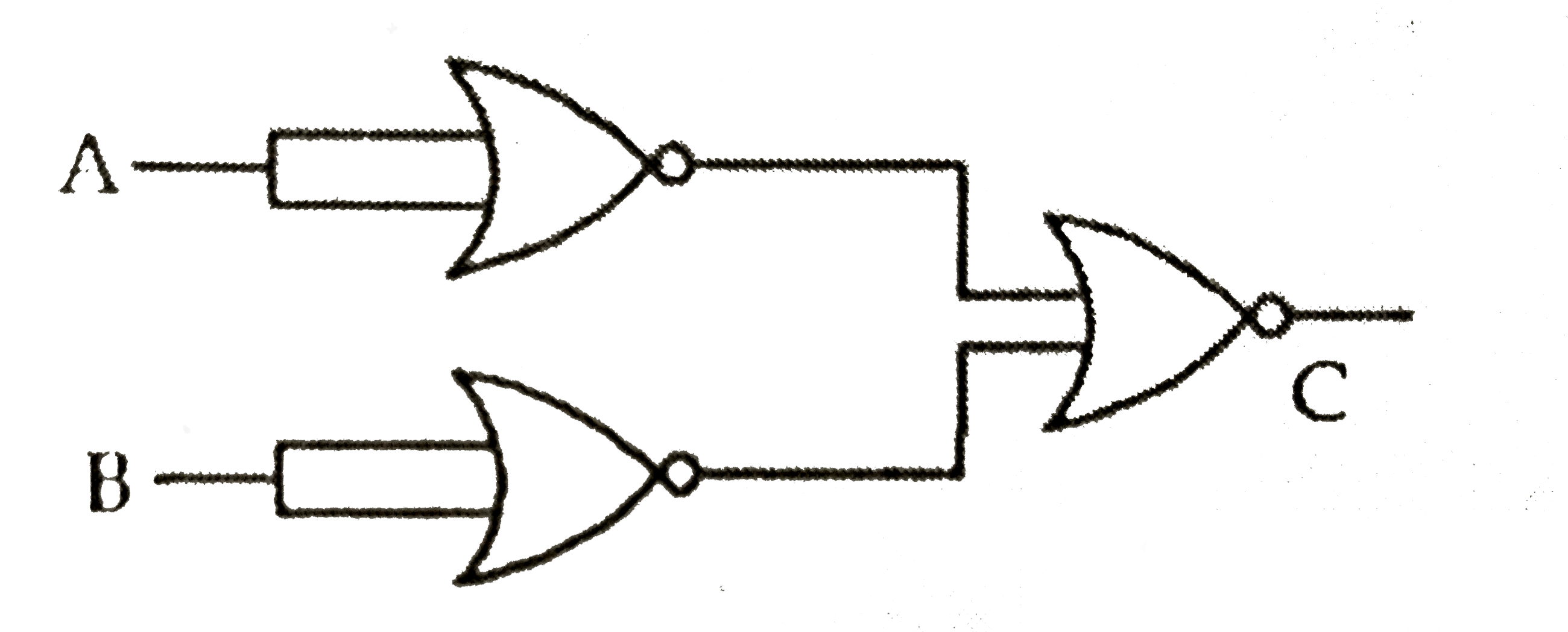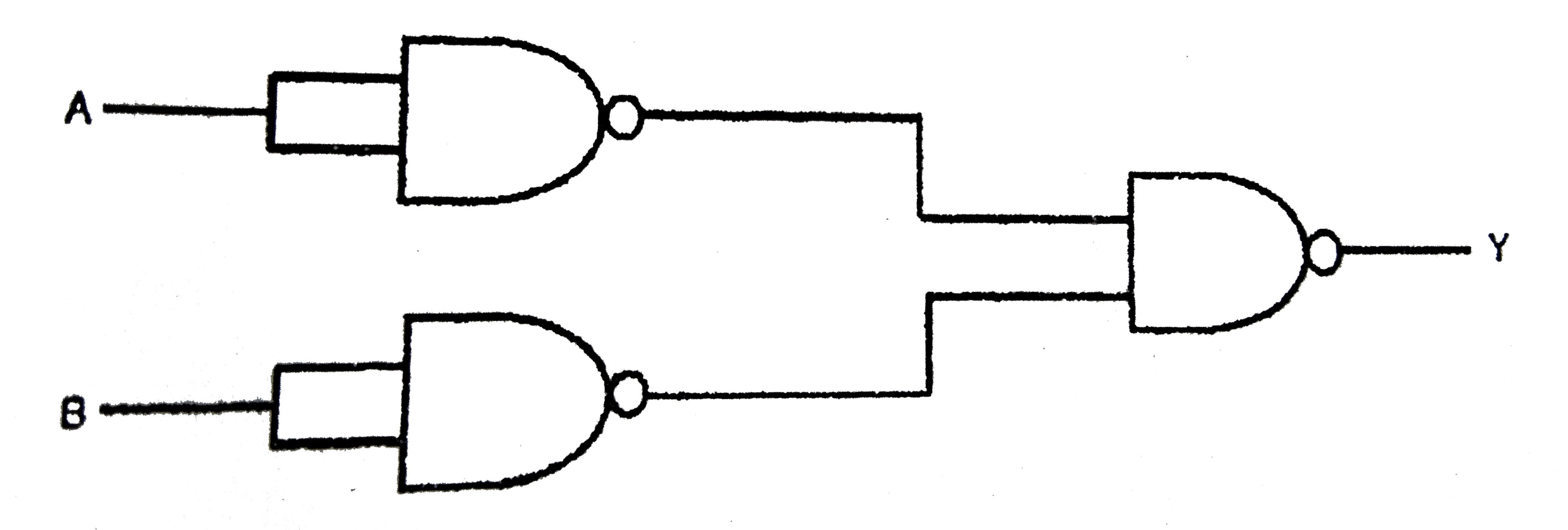
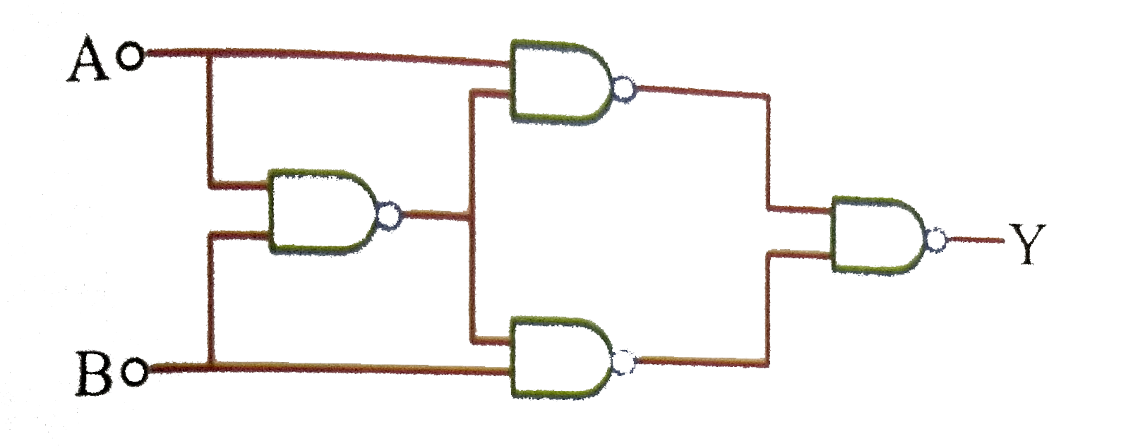
Draw the truth table for the logic gate arrangement shown in the figure.
Video Solution
Text Solution
The correct Answer is:(##RESSCEWCSPHYXIIC01E01167_A01##)

InputoutputABY=A+B000011111
From the logic gate circuit
Y=¯¯¯¯¯¯¯¯¯¯¯¯¯¯¯¯A.B
By de morgan's theorem
¯¯¯¯¯¯¯¯¯¯¯A+B=¯¯¯¯¯¯¯¯A.B
So, Y=¯¯¯¯¯¯¯¯¯¯¯¯¯¯¯¯¯¯¯¯¯¯A+B
or Y=A+B
This is Boolean expression of OR gate whose truth table is given below:
|
Updated on:21/07/2023
Topper's Solved these Questions
Similar Questions
Knowledge Check
- Question 1 - Select One
The truth table of a logic gate is a table
Agiving only the true numbersBrejecting only the wrong numbersCgiving the relation between the input and output variables of a logic gateDwhich gives all the possible input logic levels and the corresponding resultant logic levels in the output - Question 2 - Select One
The truth table for NOT gate is.
A[1100]B[1000]C[1001]D[0111] - Question 3 - Select One
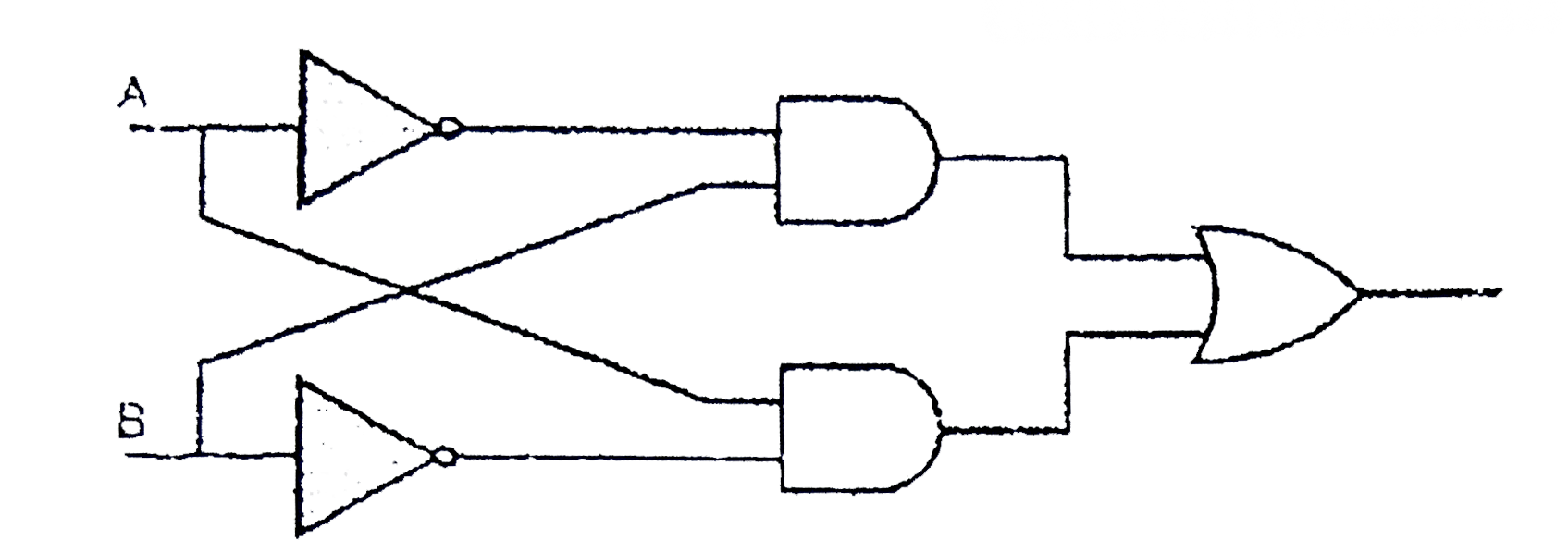
The truth table of the logic circuit shown-AABY000101101111BABY000011101110CABY001010100110DABY000100010111
Write the truth table for the circuit shown in the following figure . This circuit acts like which gate ?
 View Solution
Draw symbol and truth table for AND gate .
View SolutionTruth table for system of four NAND gates as shown in figure is
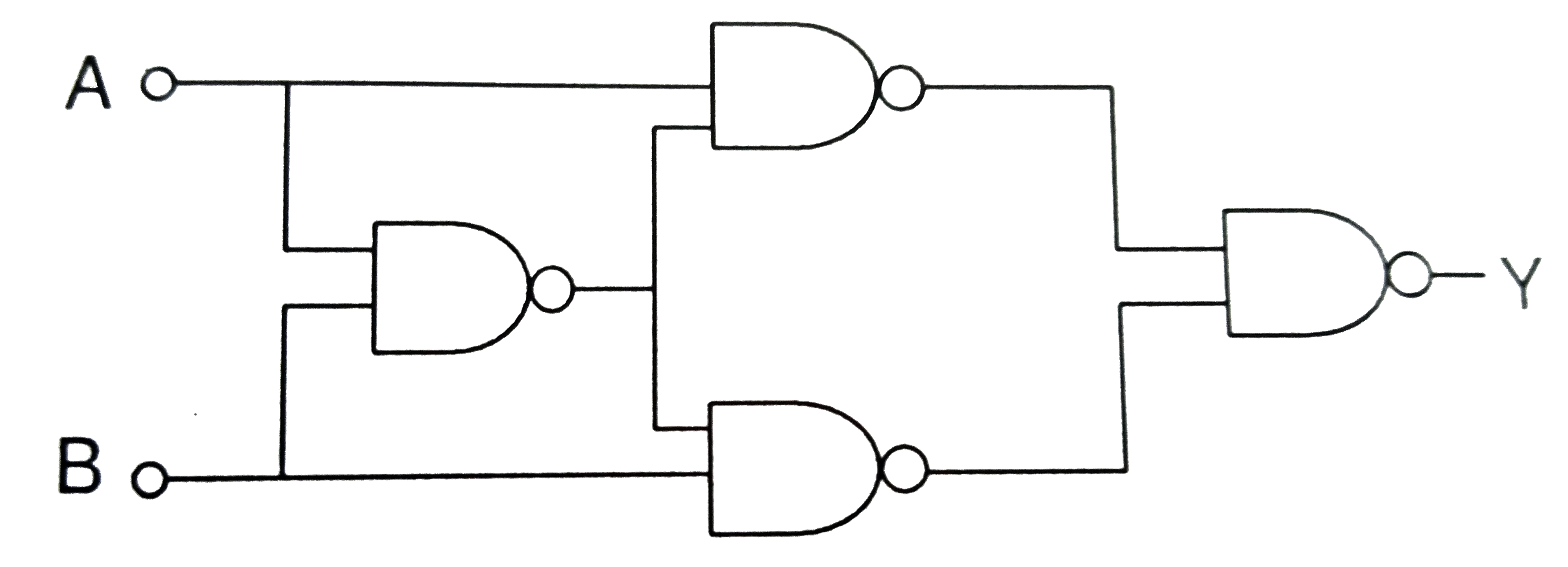 View Solution
Draw symbol and truth table for AND gate .
View SolutionTruth table for system of four NAND gates as shown in figure is :
 .View Solution


