In the situation shown in figure , an ideal ammeter is connected across 7Ωresistors. Select the correct statement from the following
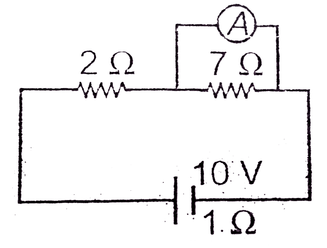
The current drawn by the battery is 1A
The currents through 2Ω and 7Ω are equal
The rate of heat production in 7Ω is less than that in 2Ω
Both (1) & (2)
The correct Answer is:3
Step by step video & image solution for In the situation shown in figure , an ideal ammeter is connected across 7 Omega resistors. Select the correct statement from the following by Physics experts to help you in doubts & scoring excellent marks in Class 12 exams.
Updated on:21/07/2023Topper's Solved these Questions
- CURRENT ELECTRICITYBOOK - AAKASH INSTITUTECHAPTER - CURRENT ELECTRICITYEXERCISE - ASSIGNMENT SECTION-C(OBJECTIVE TYPE QUESTION ))
3 Videos
- CURRENT ELECTRICITYBOOK - AAKASH INSTITUTECHAPTER - CURRENT ELECTRICITYEXERCISE - ASSIGNMENT SECTION-E (ASSERTION-REASON TYPE QUESTION)
13 Videos
- CURRENT ELECTRICITYBOOK - AAKASH INSTITUTECHAPTER - CURRENT ELECTRICITYEXERCISE - ASSIGNMENT(SECTION-A(OBJECTIVE TYPE QUESTIONS))
59 Videos
- COMMUNICATION SYSTEMS BOOK - AAKASH INSTITUTECHAPTER - COMMUNICATION SYSTEMS EXERCISE - ASSIGNMENT SECTION D (Assertion-Reason)
10 Videos
- DUAL NATURE OF RADIATION AND MATTER BOOK - AAKASH INSTITUTECHAPTER - DUAL NATURE OF RADIATION AND MATTER EXERCISE - ASSIGNMENT (SECTION-D)
10 Videos
Similar Questions
Knowledge Check
For the circuit shown in figure, select the correct statements from the following options :
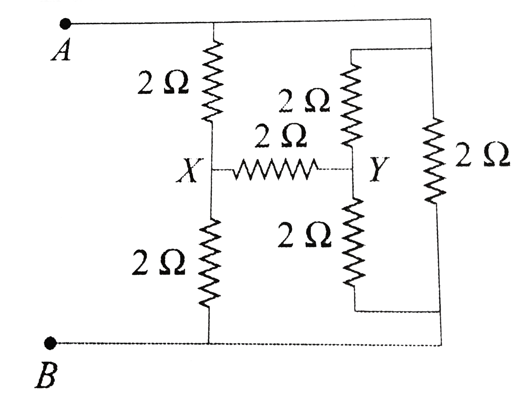 . Ax and y are equipotential points.BEffective resistance between A and B is 2Ω .CEffective resistance between A and B is 1Ω .DNone of the above.
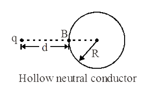
For the situation shown in the figure, select the correct statements (s).
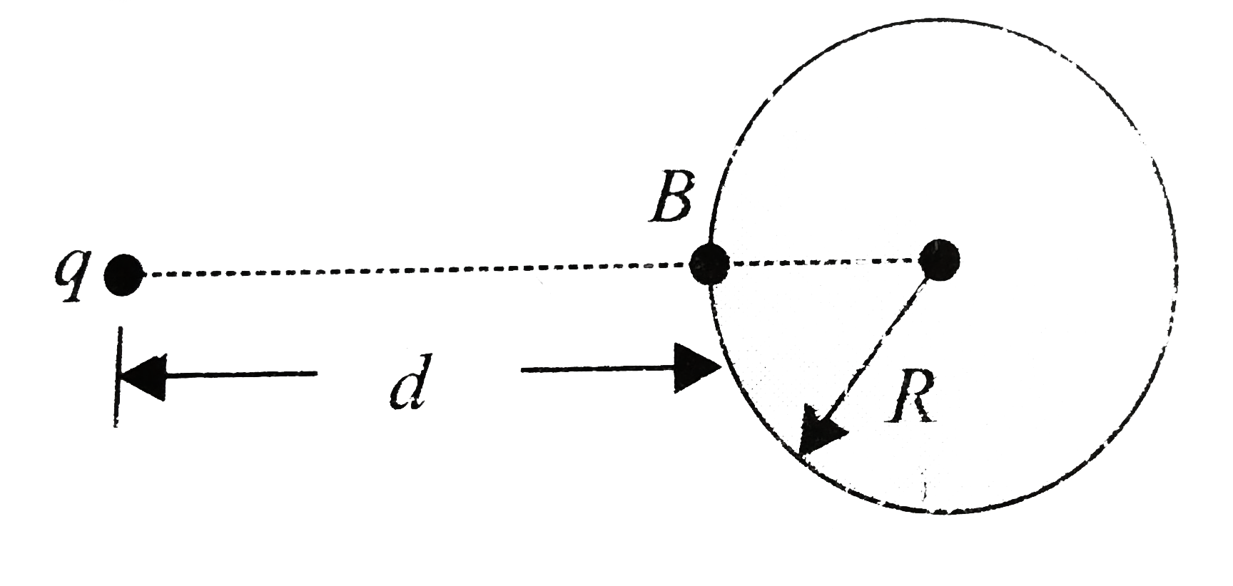 APotential of the conductor is q/4πε0(d+R)BPotential of the conductor is q/4πε0dCPotential of the conductor cannot be determined as nature of distribution of induced charges is not known.DPotential at point B due to induced charges is −qR/4πε0(d+R)d
In a circuit shown in figure, the current recorded by an ideal ammeter A is
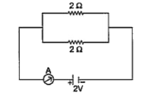 A2AB1AC0.5AD0.25A
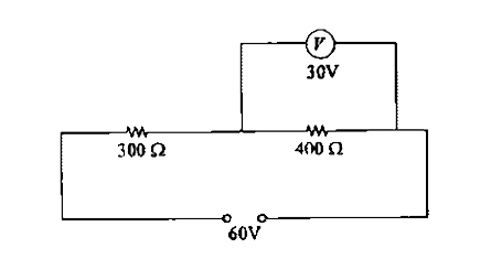
In the circuit shown in figure-3 .3 89, the voltmeter reads 30V when it is connected across 400Ω resistance. Calculate what the same voltmeter will read when it is connected across the 300Ω resistance.
View SolutionFor the situation shown in the figure below, mark out the correct statement(s) :
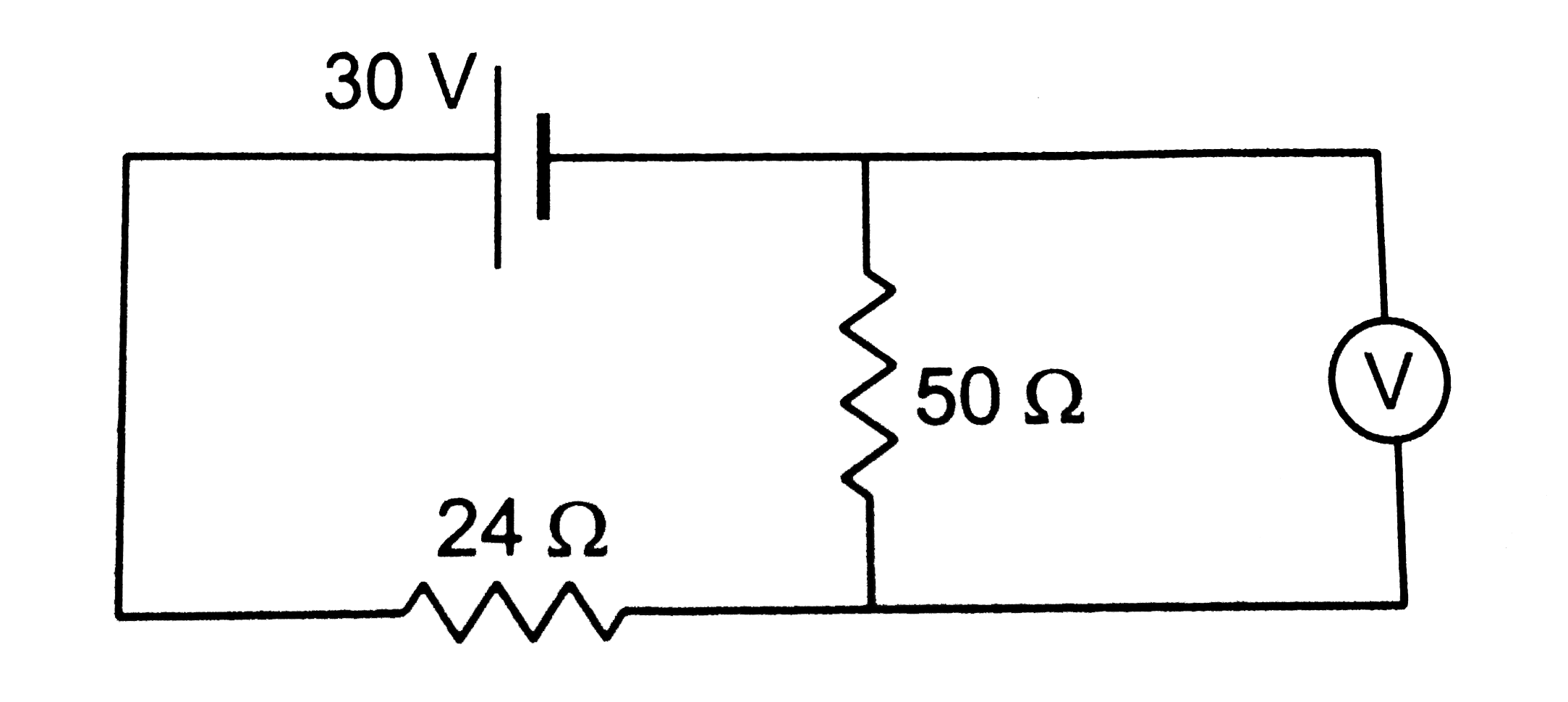
View SolutionThe voltmeter shown in figure reads 18V across the 50(Ω)resistor. Find the resistance of the voltmeter.
View SolutionShown two ideal voltmeters and an ammeter, which are connected across the various circuit elements. If the voltmeter connected across 9Ω resistance reads 4.5 V, then answer the following problems.
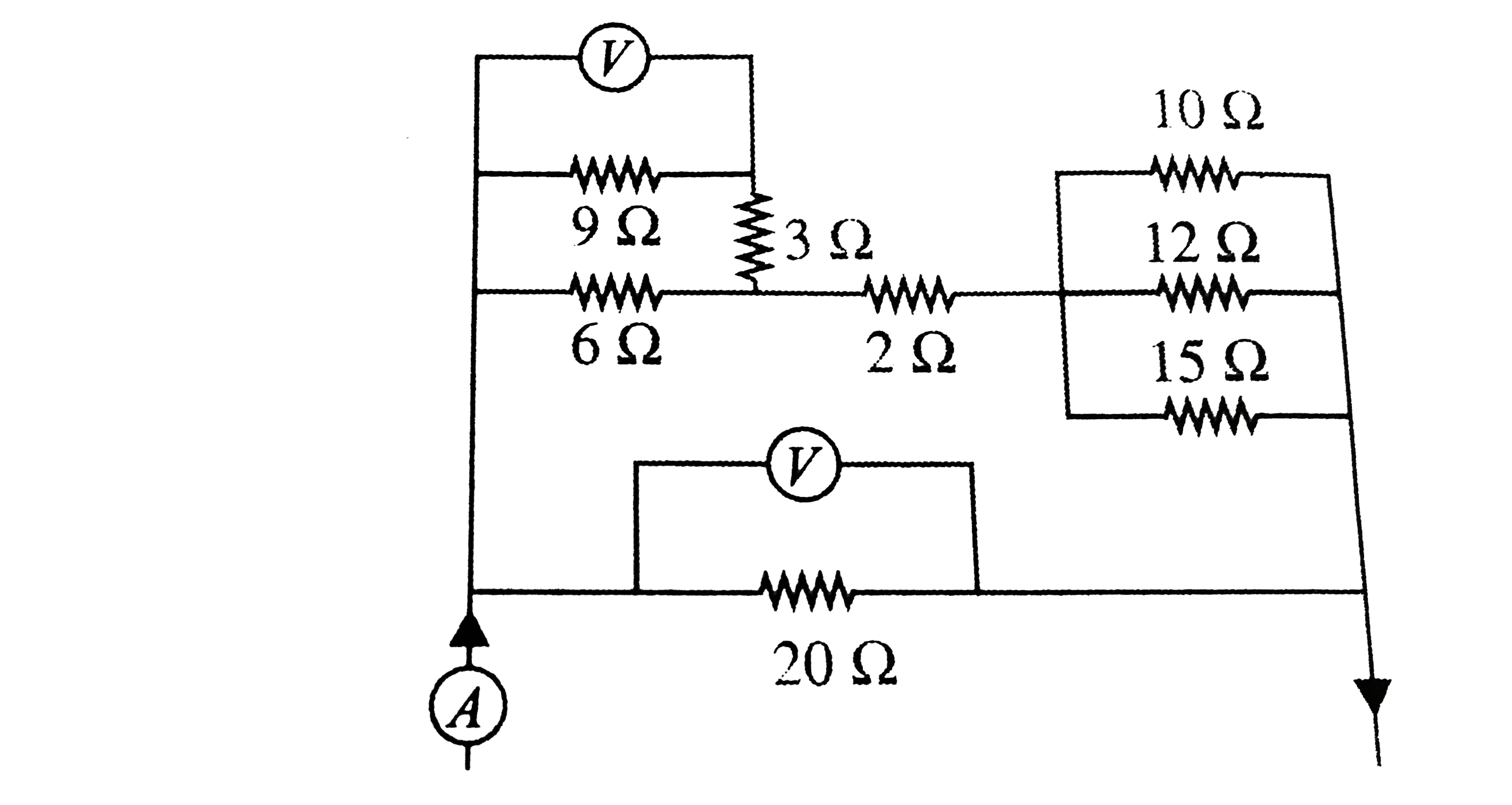
The reading of the ammeter is
View SolutionShown two ideal voltmeters and an ammeter, which are connected across the various circuit elements. If the voltmeter connected across 9Ω resistance reads 4.5 V, then answer the following problems.
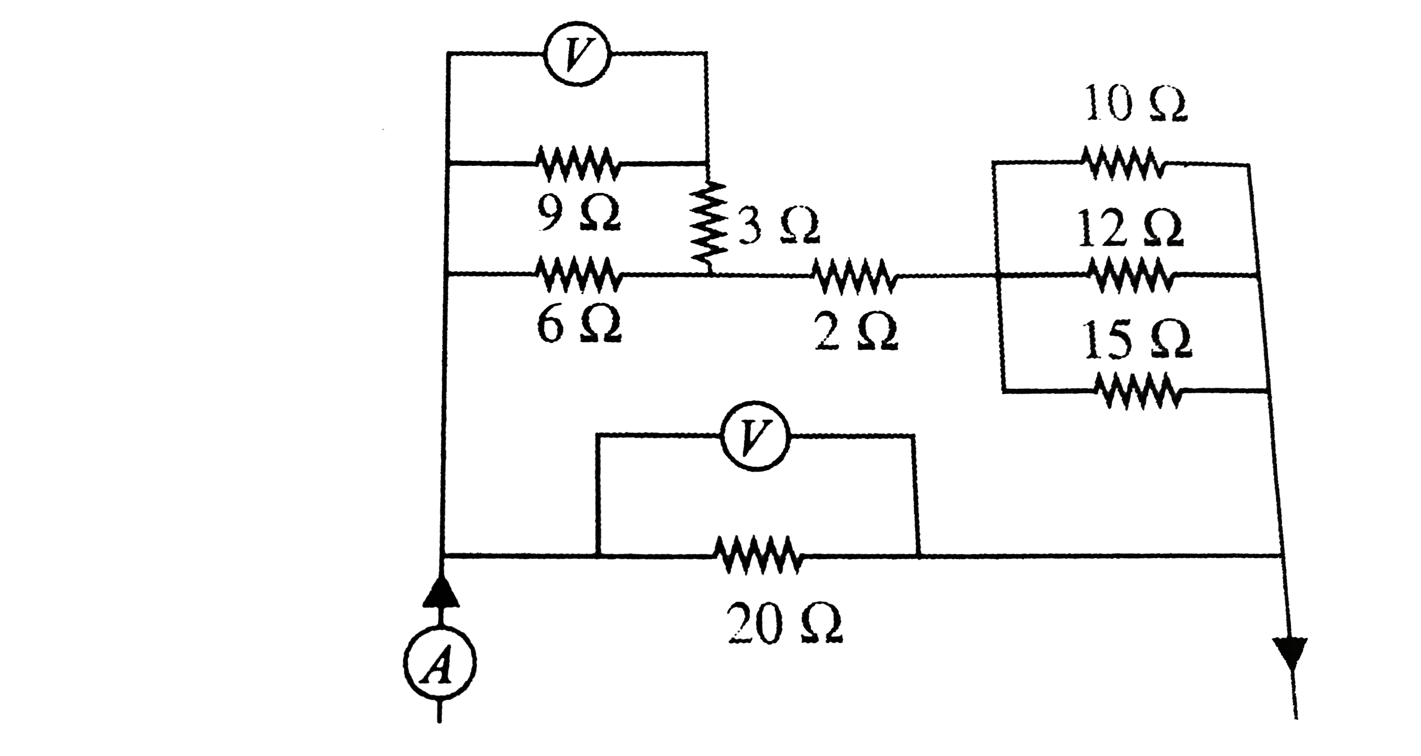
The reading of the voltmeter connected across 20Ω resistance is
View Solution

