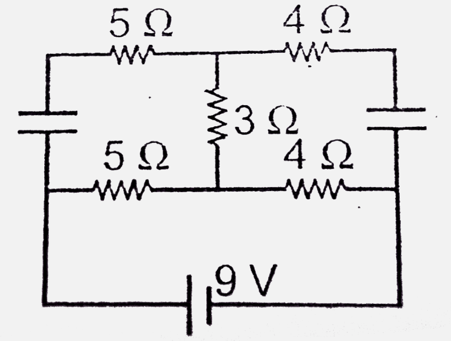
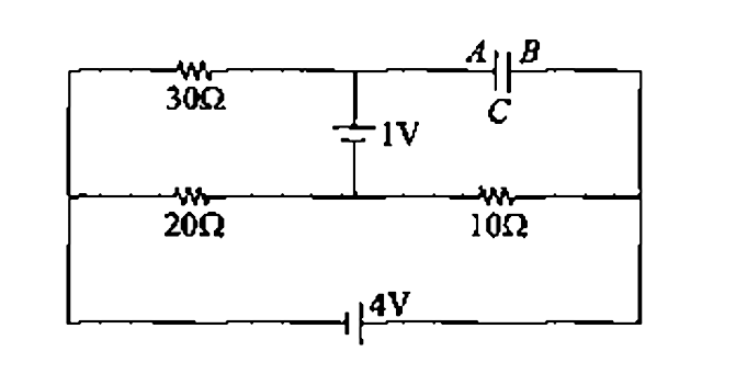
The power consumption by the circuit shown in figure at steady state is
A
18W
B
4.5 W
C
36 W
D
9W
Video Solution
Text Solution
The correct Answer is:D
|
Answer
Step by step video & image solution for The power consumption by the circuit shown in figure at steady state is by Physics experts to help you in doubts & scoring excellent marks in Class 12 exams.
Updated on:21/07/2023Topper's Solved these Questions
- CURRENT ELECTRICITYBook:AAKASH INSTITUTEChapter:CURRENT ELECTRICITYExercise:ASSIGNMENT SECTION-C(OBJECTIVE TYPE QUESTION ))
Explore 3 Videos
- CURRENT ELECTRICITYBook:AAKASH INSTITUTEChapter:CURRENT ELECTRICITYExercise:ASSIGNMENT SECTION-E (ASSERTION-REASON TYPE QUESTION)
Explore 13 Videos
- CURRENT ELECTRICITYBook:AAKASH INSTITUTEChapter:CURRENT ELECTRICITYExercise:ASSIGNMENT(SECTION-A(OBJECTIVE TYPE QUESTIONS))
Explore 59 Videos
- COMMUNICATION SYSTEMS Book:AAKASH INSTITUTEChapter:COMMUNICATION SYSTEMS Exercise:ASSIGNMENT SECTION D (Assertion-Reason)
Explore 10 Videos
- DUAL NATURE OF RADIATION AND MATTER Book:AAKASH INSTITUTEChapter:DUAL NATURE OF RADIATION AND MATTER Exercise:ASSIGNMENT (SECTION-D)
Explore 10 Videos
Similar Questions
Knowledge Check
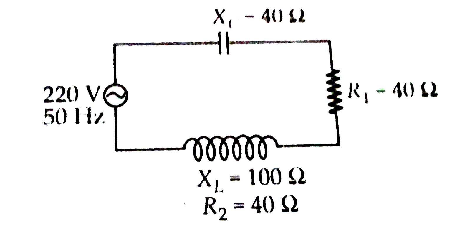
The power factor of the circuit as shown in figure is
 A0.2B0.4C0.8D0.6
The power factor of the circuit shown in the figure is
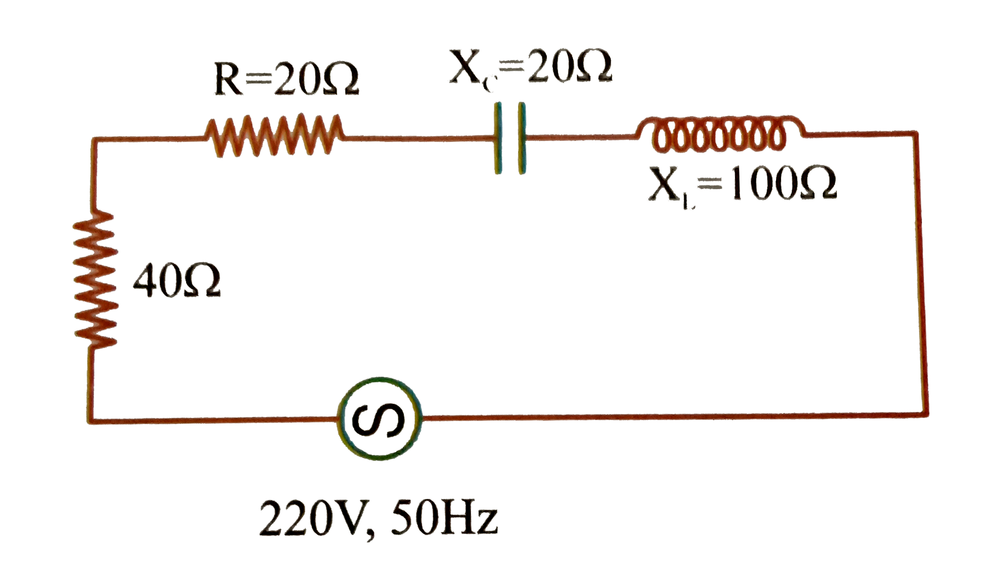 A0.4B0.2C0.8D0.6
In the circuit shown in figure, power generated in
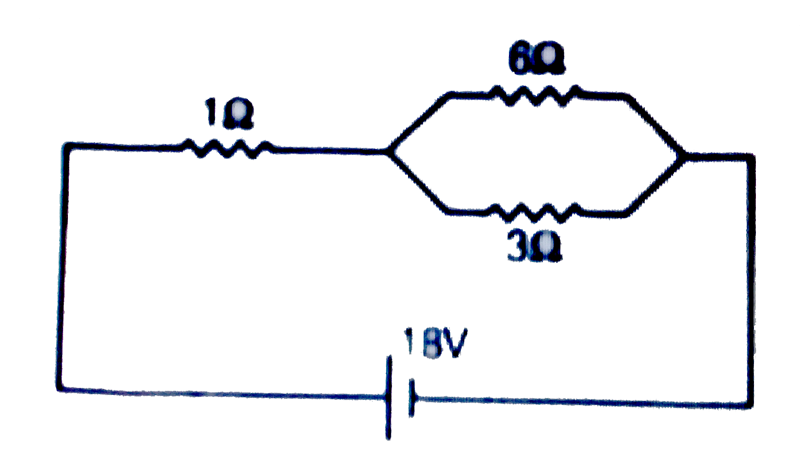 A1Ω resistance is maximumB3Ω resistance is maximumC1Ω resistance is minimumD6Ω resistance is minimum
Find the power factor of the circuit shown in figure.
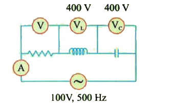
View SolutionFind the power factor of the circuit shown in figure.

View SolutionCalculate the power factor of the circuit shown in figure
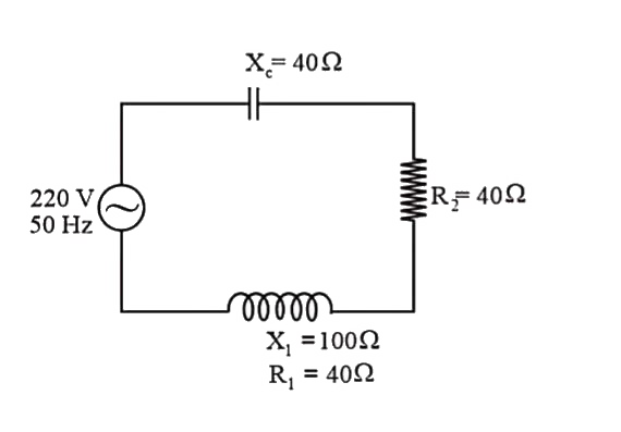
View SolutionFind the potential difference between the plates of the capacitor C in the circuit shown in figure-3.161 in steady state. The internal resistances of the cells are negligible.
View SolutionCalculate the charge on capacitor A in the circuit shown in figure-3.255 in steady state.

View Solution
