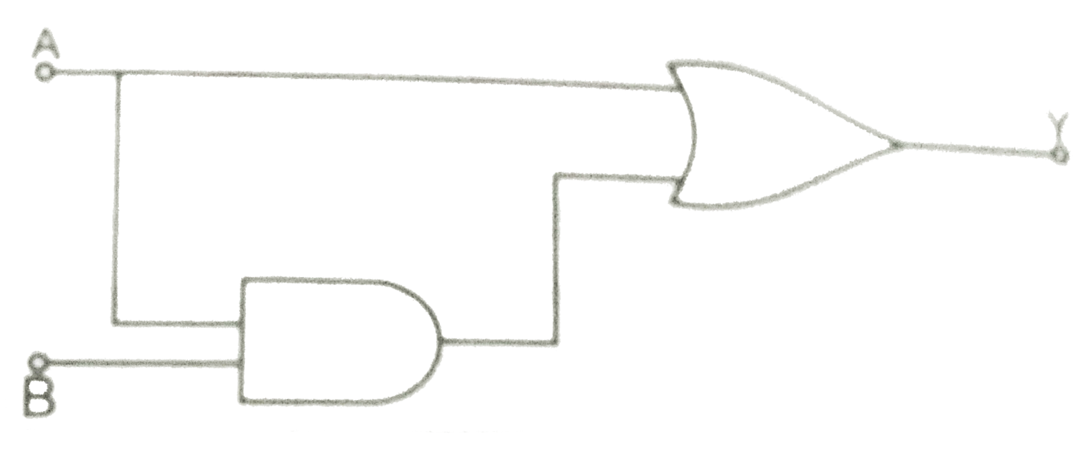
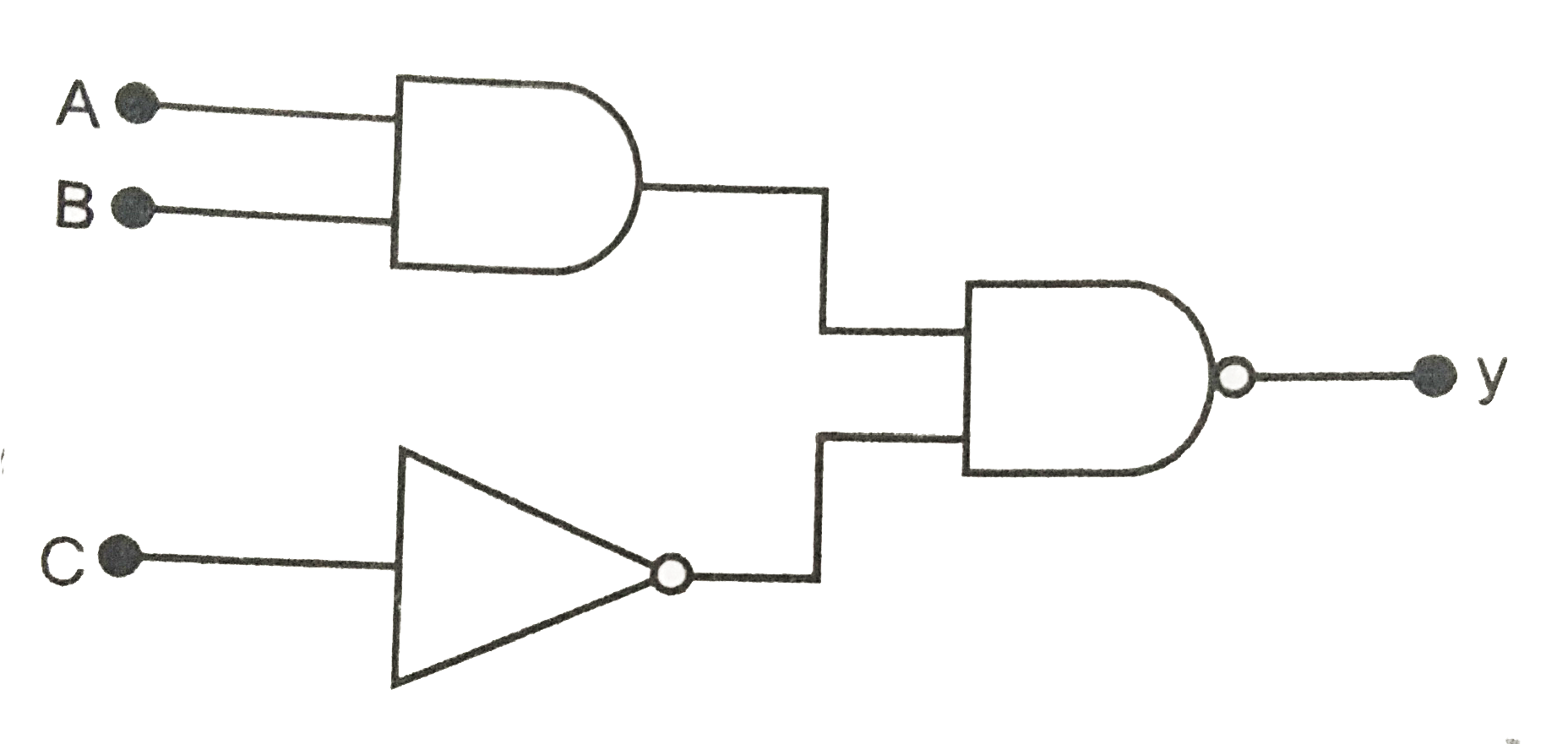
In the following circuit, the output for all possible inputs and is expressed by the truth table:

The correct Answer is:C
Step by step video, text & image solution for In the following circuit, the output Y for all possible inputs A and B is expressed by the truth table: by Physics experts to help you in doubts & scoring excellent marks in Class 11 exams.
Updated on:21/07/2023Topper's Solved these Questions
- SEMICONDUCTORSBook:ALLENChapter:SEMICONDUCTORSExercise:Part-3(Exercise-3)
Explore 27 Videos
- SEMICONDUCTORSBook:ALLENChapter:SEMICONDUCTORSExercise:Part-3(Exercise-4)
Explore 51 Videos
- SEMICONDUCTORSBook:ALLENChapter:SEMICONDUCTORSExercise:Part-3(Exercise-1)
Explore 84 Videos
- PHYSICAL WORLD, UNITS AND DIMENSIONS & ERRORS IN MEASUREMENT Book:ALLENChapter:PHYSICAL WORLD, UNITS AND DIMENSIONS & ERRORS IN MEASUREMENT Exercise:EXERCISE-IV
Explore 8 Videos
- WAVES AND OSCILLATIONSBook:ALLENChapter:WAVES AND OSCILLATIONSExercise:Part-1(Exercise-05)[B]
Explore 42 Videos
Similar Questions
Knowledge Check
In the following circuit the output Y becomes zero for the inputs
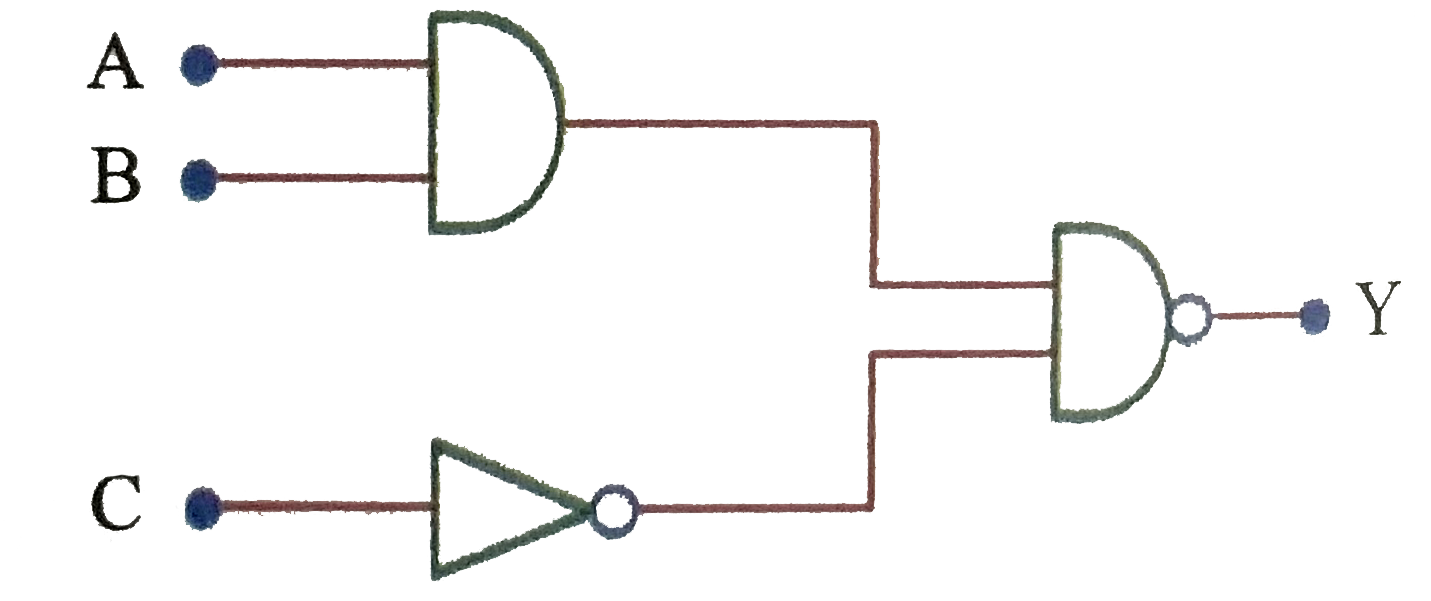 .AA=1,B=0,C=0BA=0,B=1,C=1CA=0,B=0,C=0DA=1,B=1,C=0
For the logic circuit shown, the truth table is
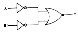 A
A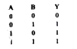 B
B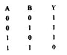 C
C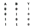 D
D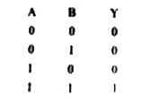
In AND gate, the output Y is 1 when the inputs A and B are:
AA=1, B=0BA=1, B=1CA=0, B=0DA=0, B=1
The Boolean expression of the output Y of the inputs A and B for the circuit shown in the fig.
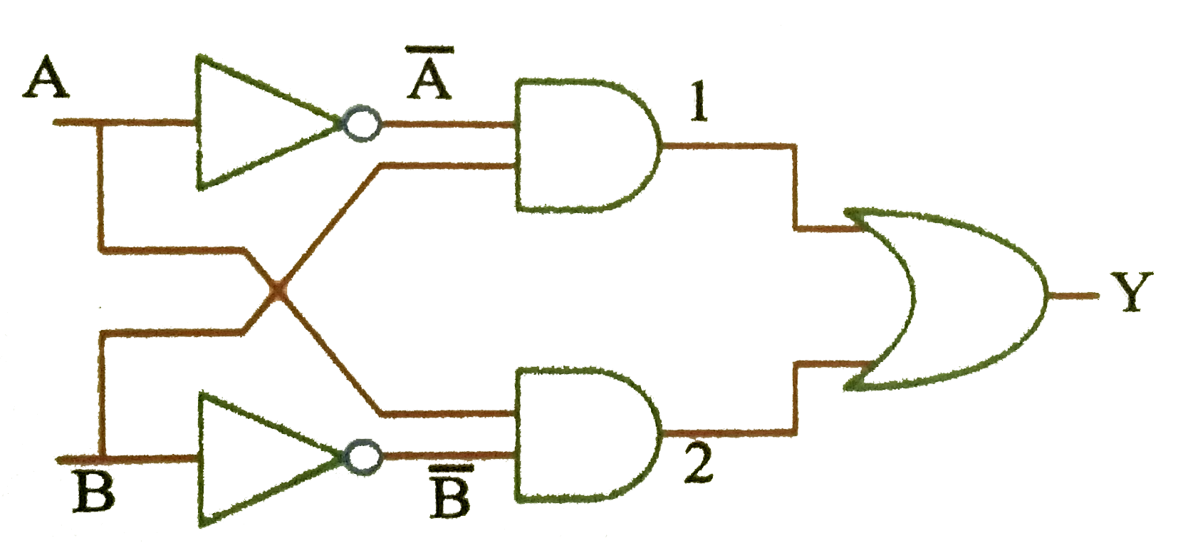 .
.
View SolutionIn the logic circuit shown in the figure, if input A and B are 0 to 1 respectively, the output at Y would be ‘x’
The value of x is _______

View SolutionWhich of the following is the truth table for the circuit below ?

View SolutionThe Boolean expression of the output Y of the inputs A and B for the circuit shown in the fig.
 .
.
View SolutionIn the circuit Fig. the output y becomes zero for the inputs
View Solution
