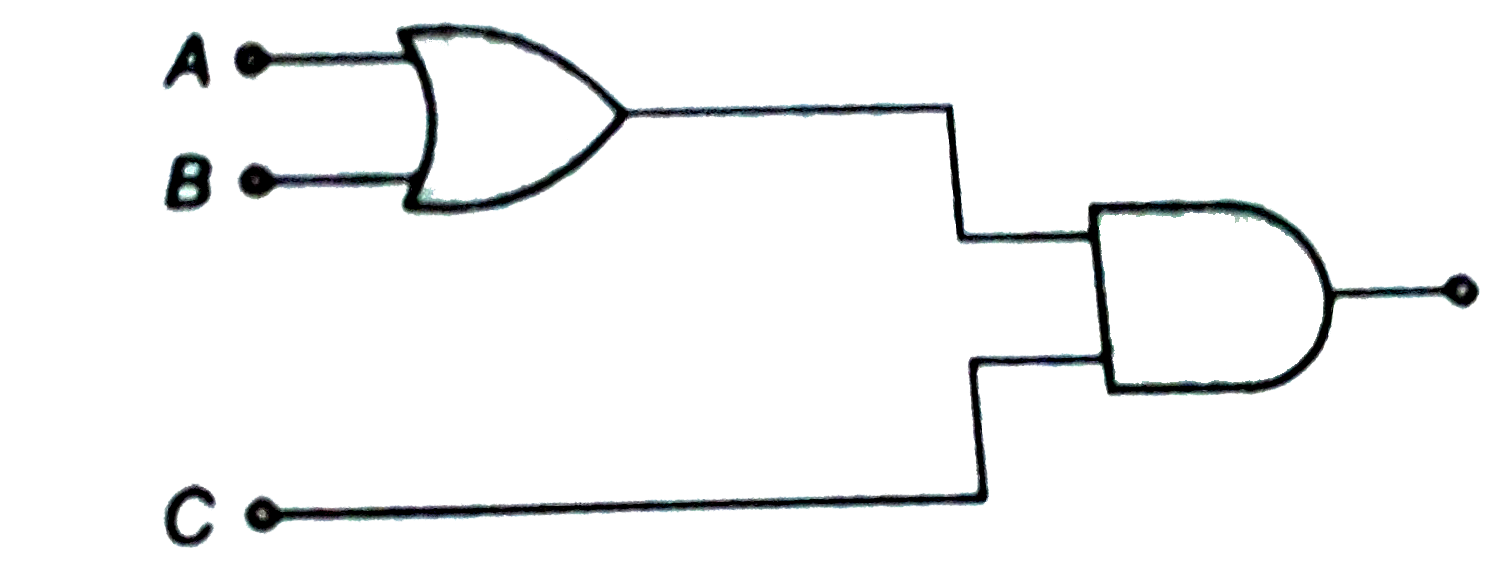
In the logic circuit shown in the figure, if input A and B are 0 to 1 respectively, the output at Y would be ‘x’
The value of x is _______

Video Solution
|
Answer
Step by step video & image solution for In the logic circuit shown in the figure, if input A and B are 0 to 1 respectively, the output at Y would be ‘x’ The value of x is "_______" by Physics experts to help you in doubts & scoring excellent marks in Class 12 exams.
Updated on:21/07/2023Topper's Solved these Questions
- JEE MAIN 2021BOOK - JEE MAINS PREVIOUS YEARCHAPTER - JEE MAIN 2021EXERCISE - PHYSICS SECTION A
60 Videos
- JEE MAIN 2021BOOK - JEE MAINS PREVIOUS YEARCHAPTER - JEE MAIN 2021EXERCISE - PHYSICS SECTION B
30 Videos
- JEE MAIN 2021BOOK - JEE MAINS PREVIOUS YEARCHAPTER - JEE MAIN 2021EXERCISE - PHYSICS (SECTION A)
60 Videos
- JEE MAINBOOK - JEE MAINS PREVIOUS YEARCHAPTER - JEE MAINEXERCISE - All Questions
473 Videos
- JEE MAIN 2022BOOK - JEE MAINS PREVIOUS YEARCHAPTER - JEE MAIN 2022EXERCISE - Question
492 Videos
Similar Questions
Knowledge Check
The output Y of the logic circuit as shown in figure is
 A(A+B)⋅¯¯¯CB(A+C)⋅¯¯¯CC(B+C)⋅¯¯¯ADA+B+C
The output (X) of the logic circuit shown in figure will be
 AX=A.BBX=¯¯¯¯¯¯¯¯¯¯¯A+BCX=¯¯¯¯¯¯¯A.¯¯¯¯¯¯BDX=¯¯¯¯¯¯¯¯A.B
The output (X) of the logic circuit shown in figure will be
 AX=¯¯¯¯¯¯¯A.¯¯¯¯¯¯BBX=¯¯¯¯¯¯¯¯A.BCX=A.BDX=¯¯¯¯¯¯¯¯¯¯¯A+B
To get an output 1 from the circuit shown in the figure, the input must be

View SolutionTo get an output 1 from the circuit shown in the figure, the input must be

View SolutionThe output (X) of the logic circuit shown in figure will be

View SolutionThe output Y of the logic circuit as shown in figure is best represents as

View SolutionThe output Y of the gate circuit shown in the figure below is

View Solution


