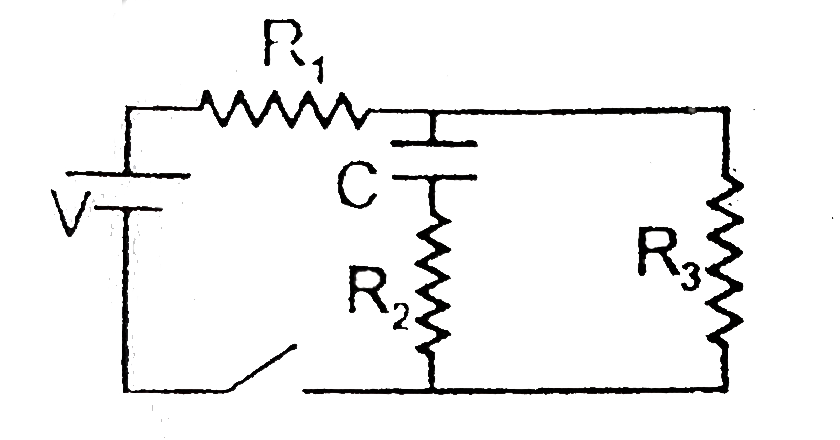
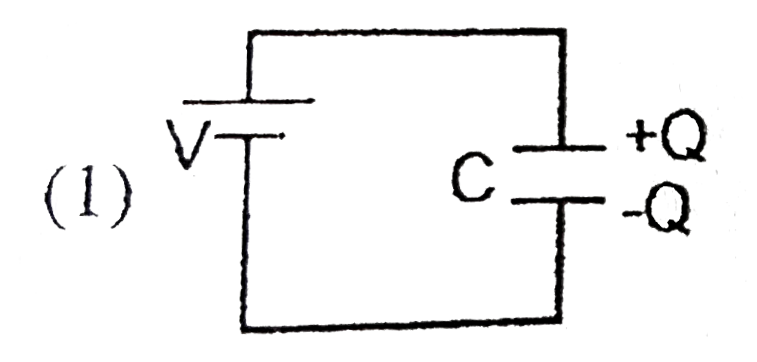
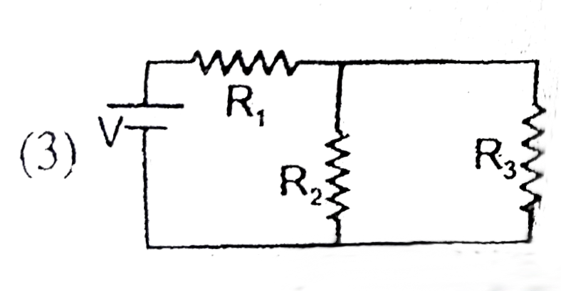
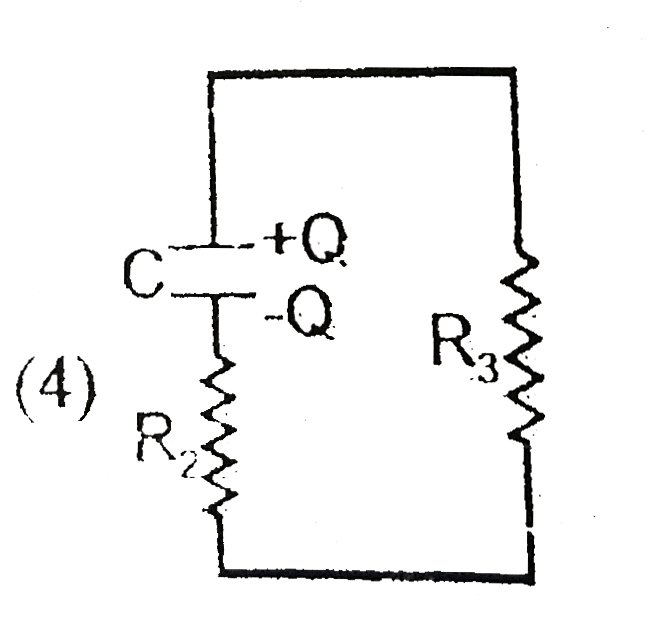
Consider the shown circuit. The capacitor is uncharged when the swith is closed at time t=0. Which of the circuit given in option is equivalent to the shown circuit as t approaches infinity?
A
B

C
D
Video Solution
Text Solution
The correct Answer is:B
Capacitor behaves as open circuit (when charged completely) after a long time.
|
Updated on:21/07/2023
Topper's Solved these Questions
- BOOK - ALLENCHAPTER - TEST PAPERSEXERCISE - PAPER 3100videos
TEST PAPERS
- BOOK - ALLENCHAPTER - TEST PAPERSEXERCISE - Part-1 Physics15videos
TEST PAPERS
- BOOK - ALLENCHAPTER - TEST PAPERSEXERCISE - MATHS18videos
TEST PAPERS
- BOOK - ALLENCHAPTER - TEST PAPER 4EXERCISE - PHYSICS45videos
TEST PAPER 4
- BOOK - ALLENCHAPTER - UNIT & DIMENSIONS, BASIC MATHS AND VECTOR EXERCISE - Exercise (J-A)7videos
UNIT & DIMENSIONS, BASIC MATHS AND VECTOR
Similar Questions
Knowledge Check
- Question 1 - Select One
The circuit as shown in figure is equivalent to
 ANOR gateBOR gateCAND gateDNAND gate
 - Question 2 - Select One
The circuit as shown in figure is equivalent to
 AOR gateBNOR gateCNAND gateDAND gate
 - Question 3 - Select One
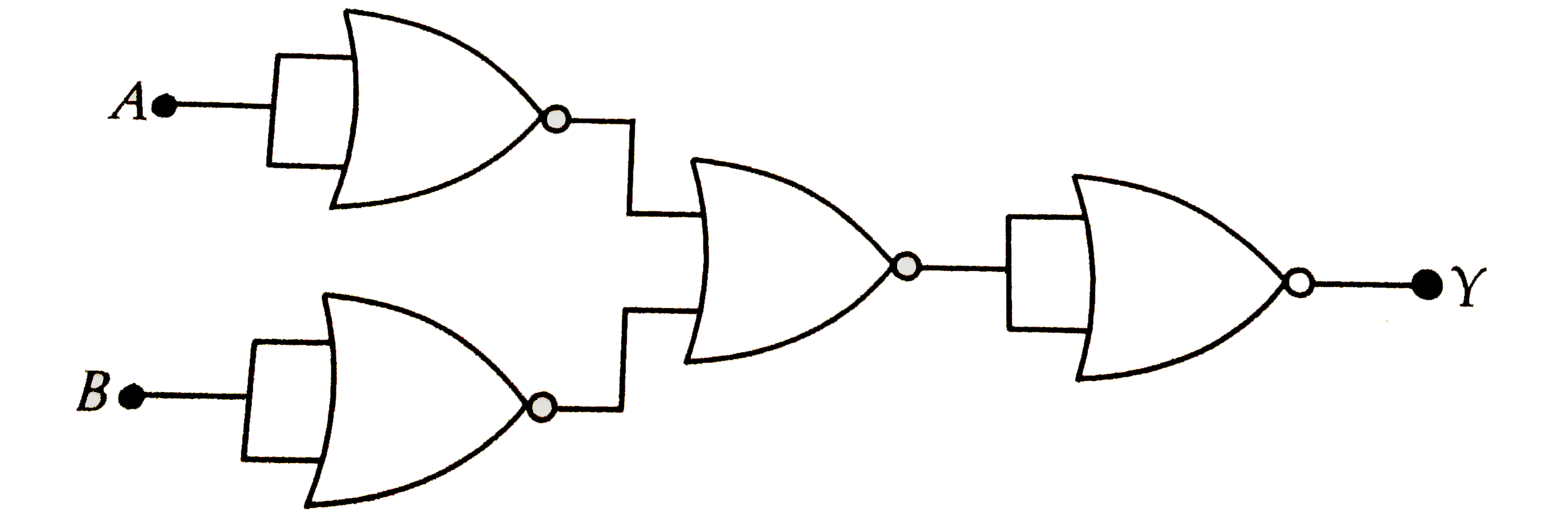
The circuit as shown in the figure is equivalent to
 AAND gateBNOT gateCOR gateDNAND gate
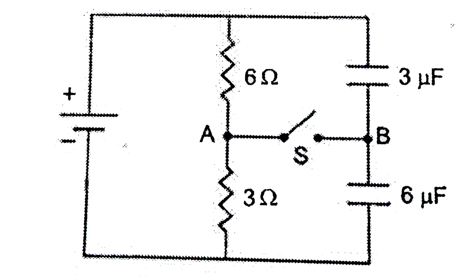
In the circuit shown above, when then switch S is closed,View Solution
The logic circuit shown above is equivalent to :View Solution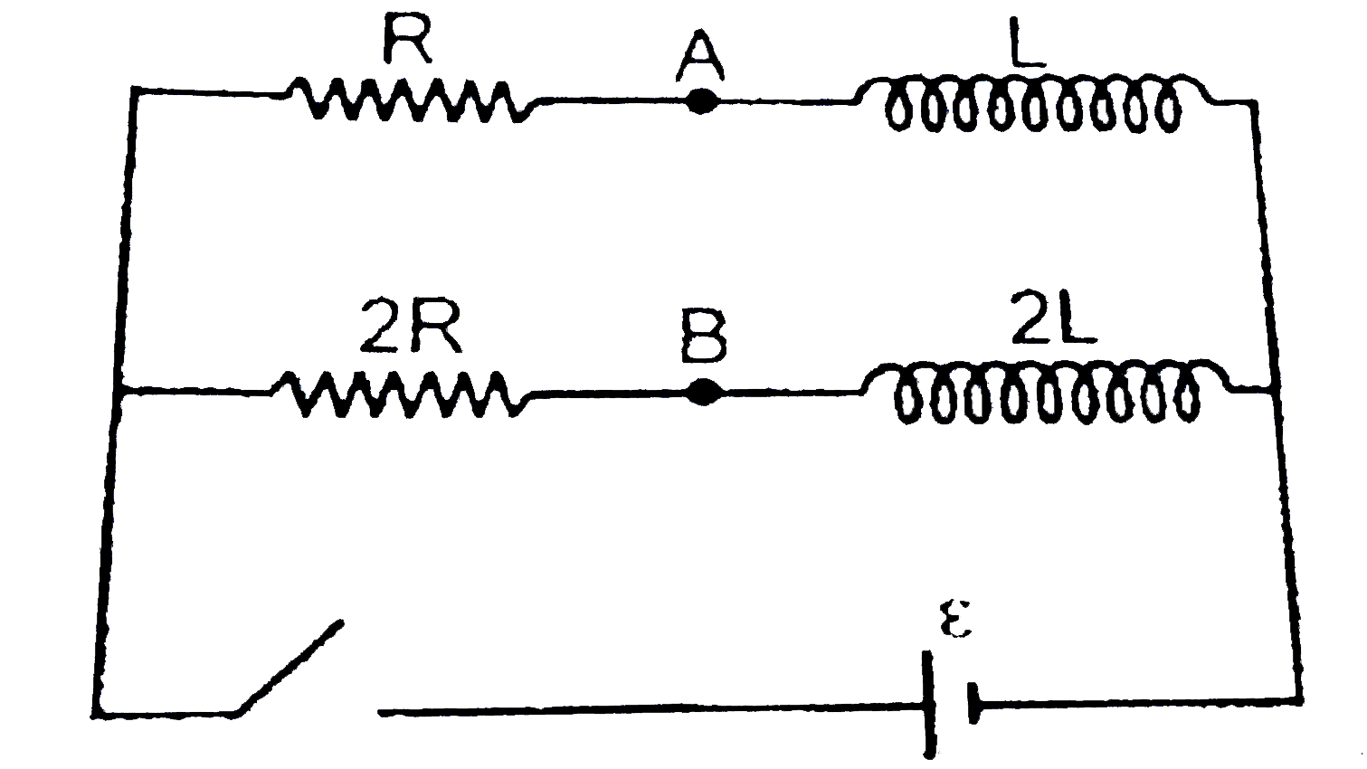
In given LR circuit the switch S is closed at time t=0 thenView SolutionFor the circuit shown, which option is incorrect
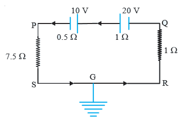 View Solution
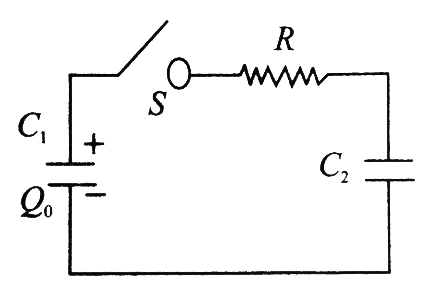
In the circuit shown, the capacitor C1 is initially charged with charge q0. The switch S is closed at time t = 0 . The charge on C2 after time t is
 View Solution

