Two ideal solenoids of same dimensions. One is air cored with 600 turns while other is Aluminium is cored with 200 turns (relative permeabililty of Aluminium is 3), are connected in a circuit as shown in the figure. The switch is closed at . Find the ratio of potential difference across air-cored solenoid to that of Aluminium cored solenoid at any time

The correct Answer is:
Since , So
Topper's Solved these Questions
- TEST PAPERSBOOK - FIITJEECHAPTER - TEST PAPERSEXERCISE - PHYSICS
747 Videos
- SIMPLE HARMONIC MOTIONBOOK - FIITJEECHAPTER - SIMPLE HARMONIC MOTIONEXERCISE - Assignment Problems (Objective) (Level-II)
20 Videos
- WORK, ENERGY AND POWER BOOK - FIITJEECHAPTER - WORK, ENERGY AND POWER EXERCISE - COMPREHENSIONS ( Comprehension-II)
5 Videos
Similar Questions
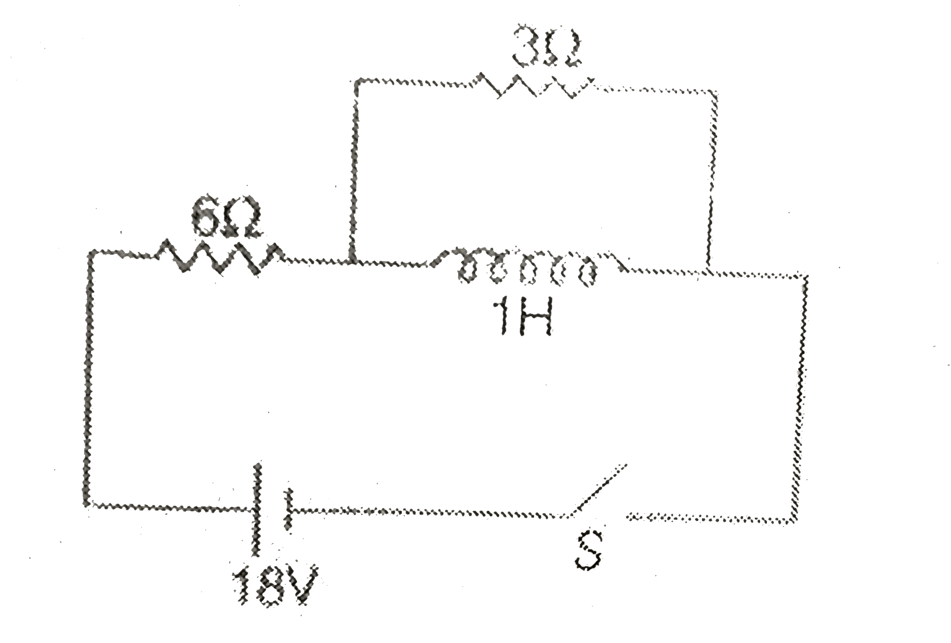
In the circuit shown in figure switch S is closed at time t=0

Potential difference across 3Ω resistance at time t is given by
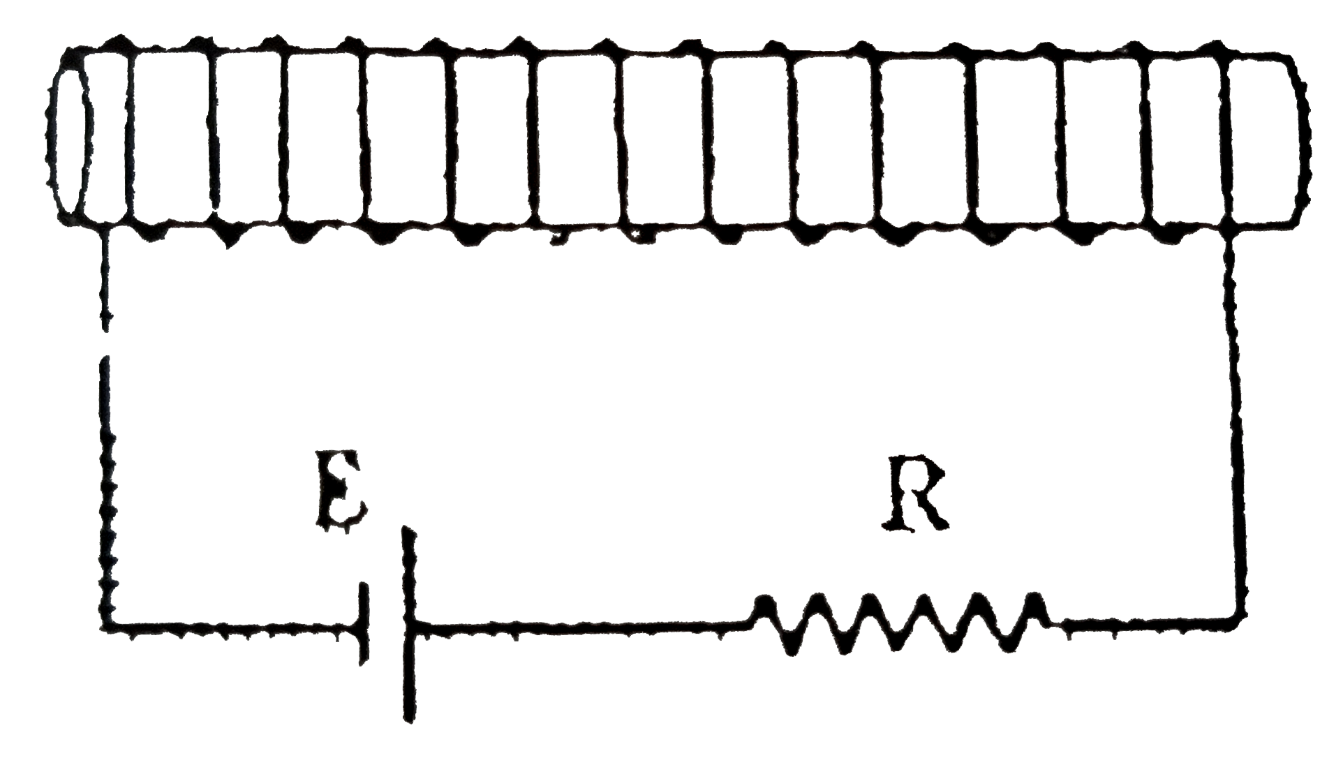
View SolutionAn iron core solenoid of length l and cross-sectional area A having N turns on it is connected to a battery through a resistance as shown in the figure. At instant t=0, the iron rod of permeability μ from the core is abruptly removed. Find the current as a function of time.

View Solution
Knowledge Check
In the circuit shown in figure switch S is closed at time t=0

Potential difference across 3Ω resistance at time t is given byA9e−21B6e−2tC3e−2tD18(1−e−t/9)An air cored solenoid with length 20 cm area of cross section 2 A. The current is suddenly switched off within 10−3 s. The average back emf induced across the ends of the open switch in the circuit is (ignore the variation in magnetic field near the ends of the solenoid)
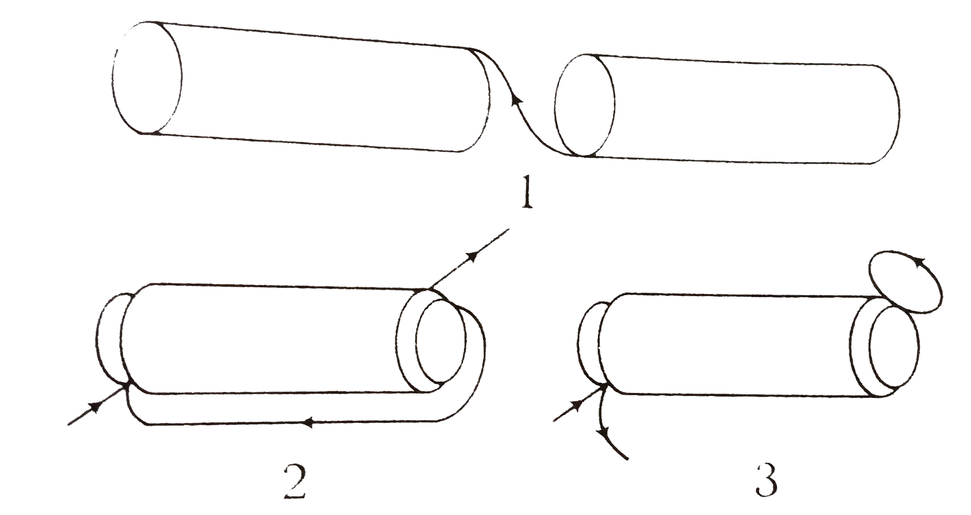
A2 VB4 VC3 VD5 VThere are two solenoid of same length and inductance L but their diameters differ to the extent that one can just fit into the other. They are connected in three different ways in series.
(1) They are connected in series but separated by large distance.
(2) They are connected in series with one inside the other and senses of the turns coinciding.
(3) Both are connected in series with one inside the other with senses of the turns opposites,
as depicted in figures 1, 2 and 3 respectively. The total inductance of the solenoids in each of the case 1, 2 and 3 are respectively.
 A0,4L0,2L0B4L0,2L0,0C2L0,0,4L0D2L0,4L0,0
An iron core solenoid of length l and cross-sectional area A having N turns on it is connected to a battery through a resistance as shown in the figure. At instant t=0, the iron rod of permeability μ from the core is abruptly removed. Find the current as a function of time.

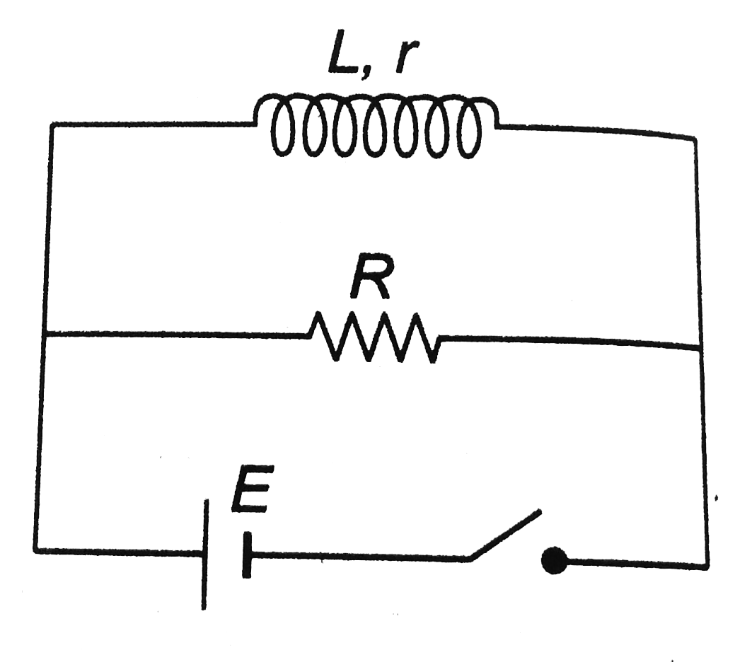
View SolutionA solenoid of inductance L with resistance r is connected in parallel to a resistance R. A battery of emf E and of negligible internal resistance is connected across the parallel combination as shown in the figure. At time t=0, switch S is opened, calculate
(a) current through the solenoid after the switch is opened.
(b) amount of heat generated in the solenoid.

View SolutionAn iron core is inserted into a solenoid 0.5 m long with 400 turns per unit length. The area of cross-section of the solenoid is 0.001m2. (a) Find the relative permeability of the core when a current of 5 A flows through the solenoid winding. Under these conditions, the magnetic flux through the cross-section of the solenoid is 1.6×10⁻³ Wb. (b) Find the inductance of the solenoid under these conditions.
View SolutionDefine self -inductance and its S.I. unit. Derive an expression for self- industance of a long, air-cored solenoid of length , radius r, and having N number of turns.
View Solution
