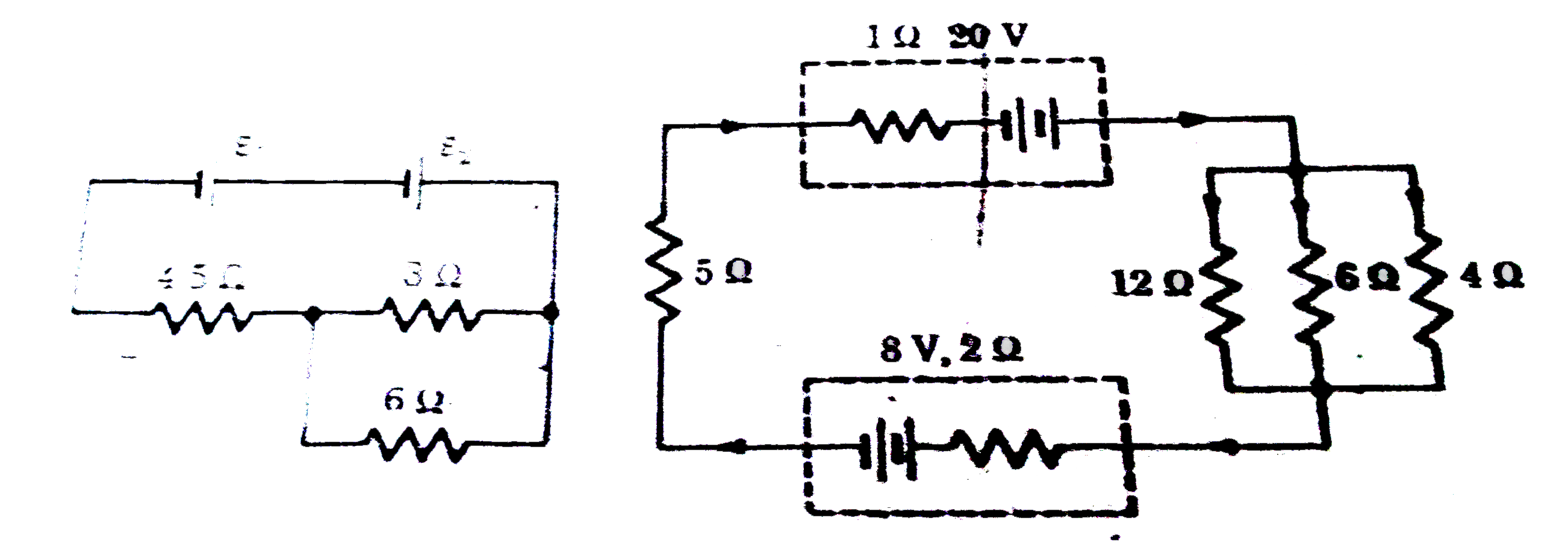
In the circuit shown ε1 and ε2 are two ideal sources of unknown emf. Some currents are shown in some branches of the circuit. Potential difference appearing across resistance 6Ω is VA−VB=10V. Then
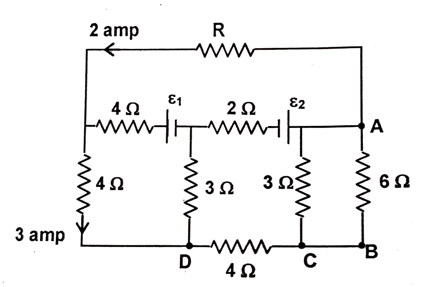
The current in the CD branch is 5 amp
The unknown emf e1 is 40 volts
The unknown emf ε2 is 68 volts
The unknown resistance R is 9Ω
The correct Answer is:A, B, C, D
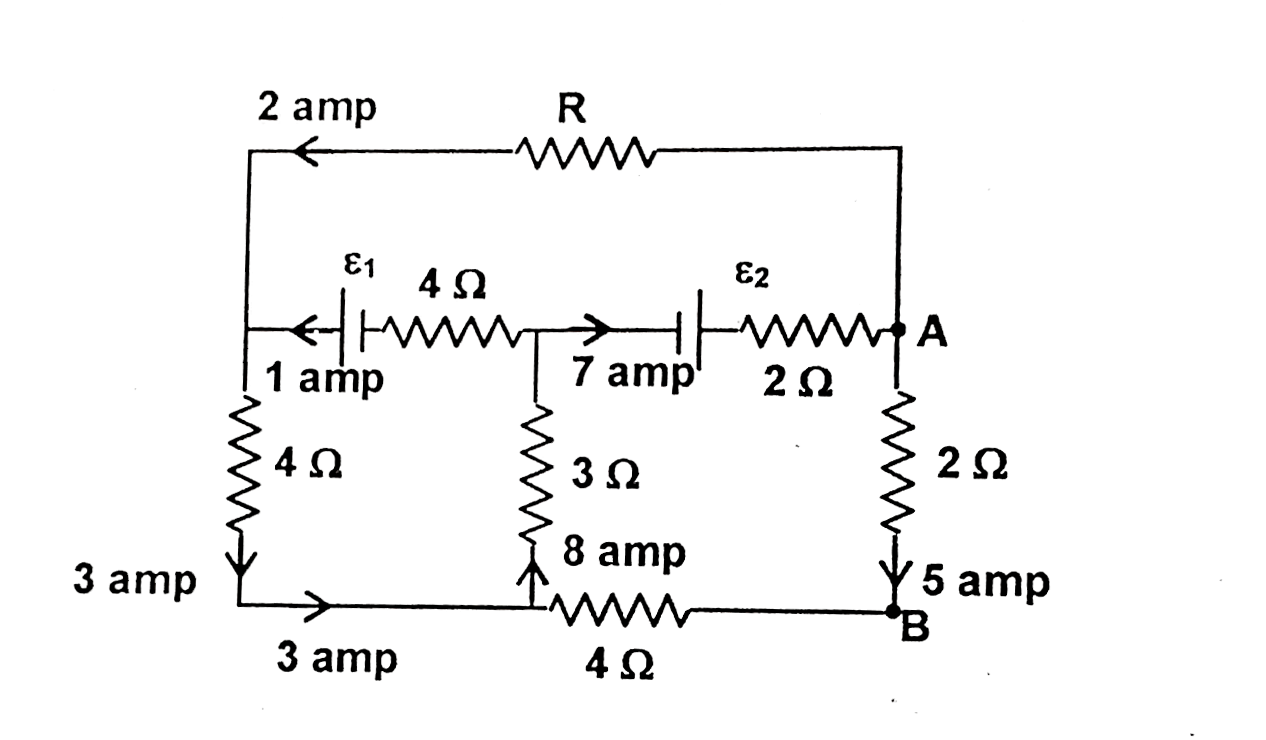
By applying Kirchhof's law
ε1=40V
ε2=68V
R=9Ω and current through 4Ω=5 amp
Topper's Solved these Questions
- TEST PAPERSBOOK - FIITJEECHAPTER - TEST PAPERSEXERCISE - PHYSICS
747 Videos
- SIMPLE HARMONIC MOTIONBOOK - FIITJEECHAPTER - SIMPLE HARMONIC MOTIONEXERCISE - Assignment Problems (Objective) (Level-II)
20 Videos
- WORK, ENERGY AND POWER BOOK - FIITJEECHAPTER - WORK, ENERGY AND POWER EXERCISE - COMPREHENSIONS ( Comprehension-II)
5 Videos
Similar Questions
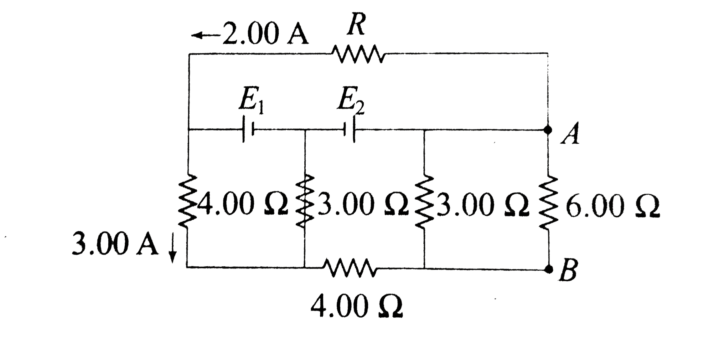
In the circuit shown in figure, E1andE2 are two ideal sources of unknown emfs. Some currents are shown. Potential difference appearing across 6Ω resistance is VA−VB=10V.
View SolutionIn the L-R circuit as shown in figure, potential difference across the resistance at some instant is 4 V. Then
View Solution
Knowledge Check
In the circuit shown in figure, E1andE2 are two ideal sources of unknown emfs. Some currents are shown. Potential difference appearing across 6Ω resistance is VA−VB=10V.
 AThe current in the 4.00Ω resistor is 5 A.BThe unknown emf E1is36V.CThe unknown emf E2is54V.DThe resistance R is equal to 9Ω.
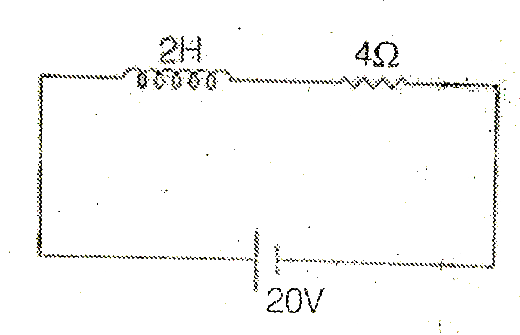
In the L-R circuit as shown in figure, potential difference across the resistance at some instant is 4 V. Then
 Acurrent is increasing at a rate of 8A/s at this instantBpower supplied by the battery at this instant is 20WCpower stored in the magnetic field at this instant is 16WDcurrent in the circuit at this instant is 1A
In the circuit shown in fig. the cell has emf 10V and internal resistance 1Ω
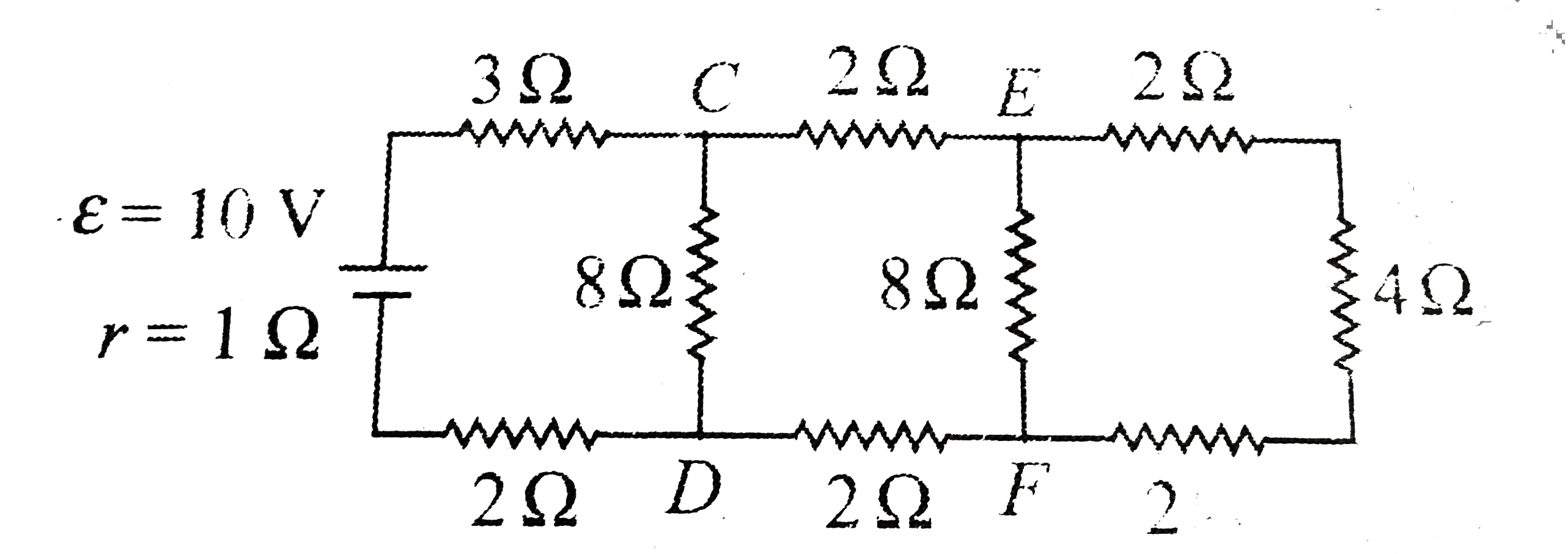 AThe current through the 3Ω resistor is 1A.BThe currents through the 3Ω resistor is 0.5 A.CThe currents through the 4Ω resistor is 0.5 ADThe current through the 4Ω resistor is 0.25 A.
In the circuit shown in fig. the cell has emf 10V and internal resistance 1Ω

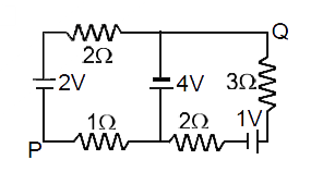
View SolutionIn the circuit shown , what is the potential difference VPQ?
View SolutionIn the circuit shown in Fig. 4.68, the cells ε1 and ε2 have emf's of 4 V and 8 V and internal resistances of 0.5Ω and 1Ω respectively. Calculate the current in each resistance.
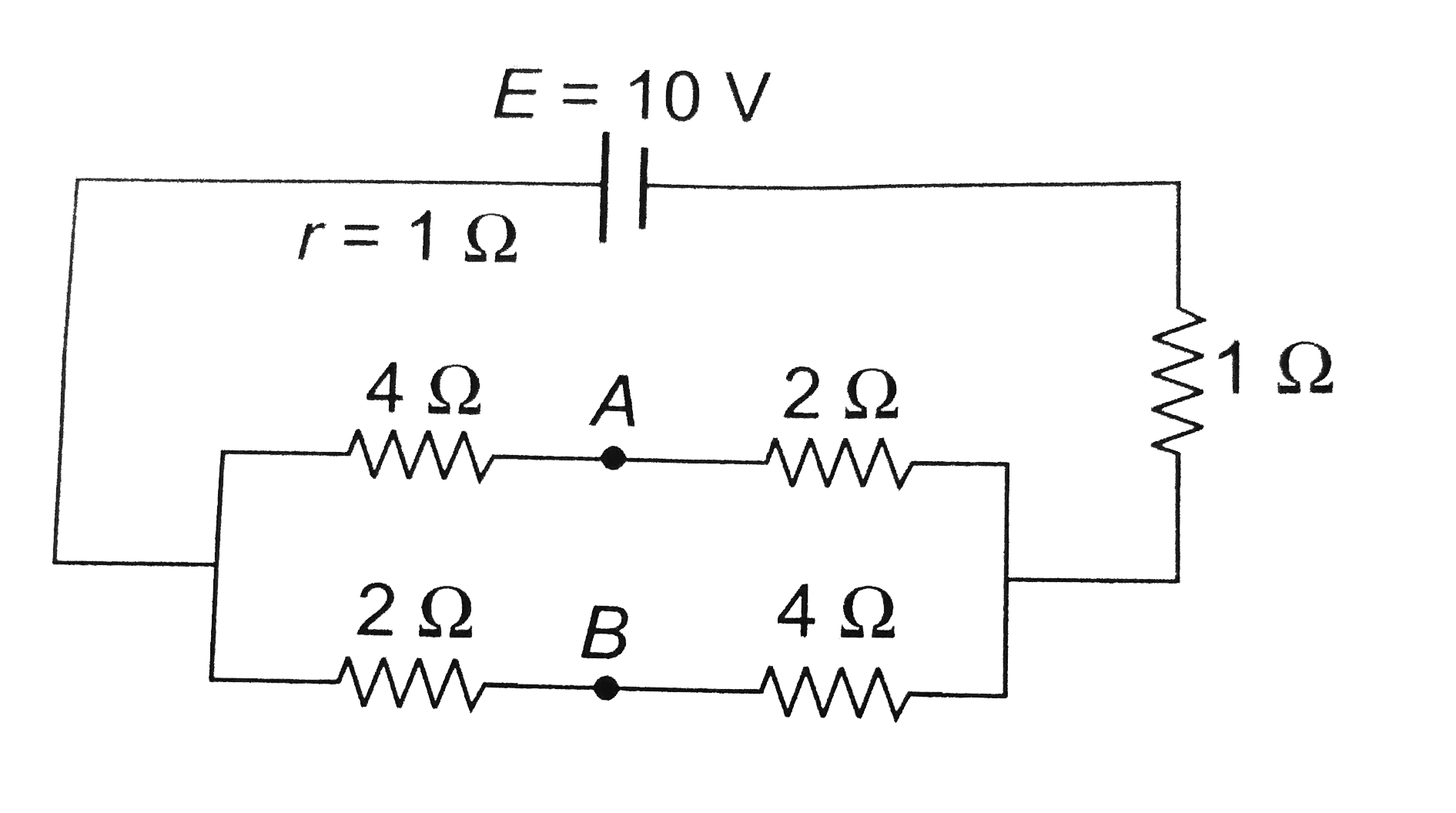
View SolutionIn the circuit shown below, the cell has an e.m.f. of 10V and internal resistance of 1ohm. The other resistances are shown in the figure. The potential difference VA−VB is
View SolutionIn the circuit shown, what is the potential difference VPQ?
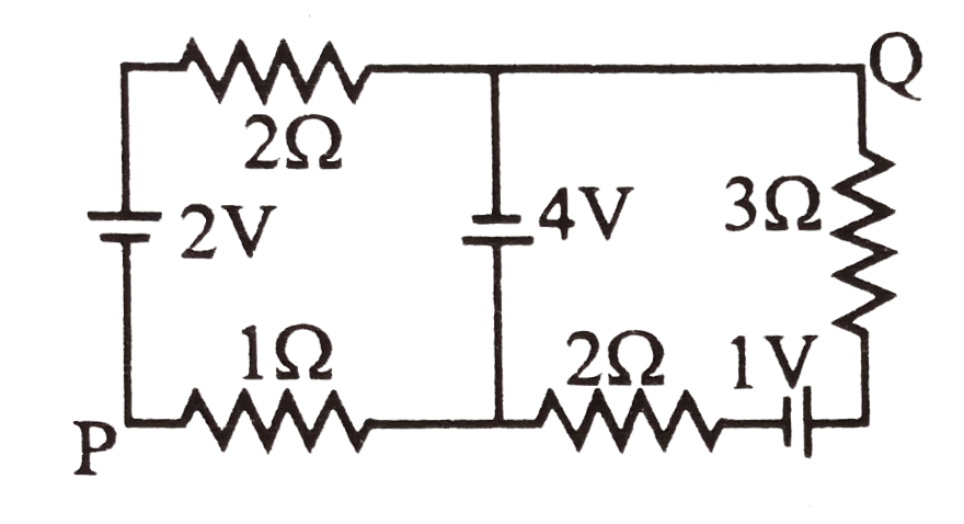
View Solution
