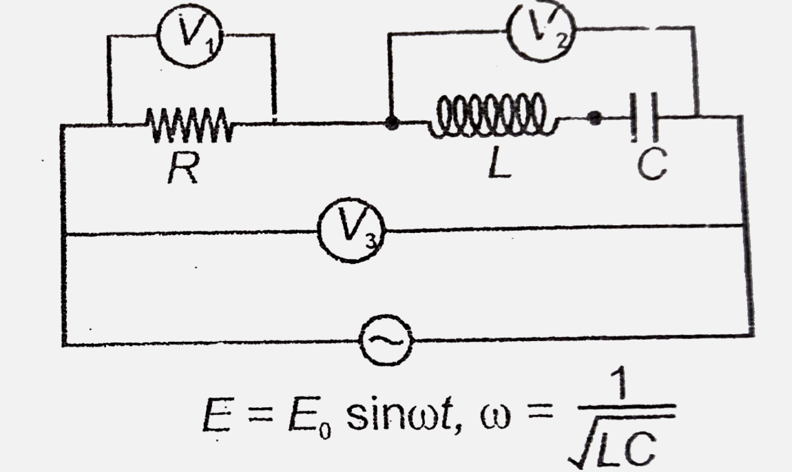
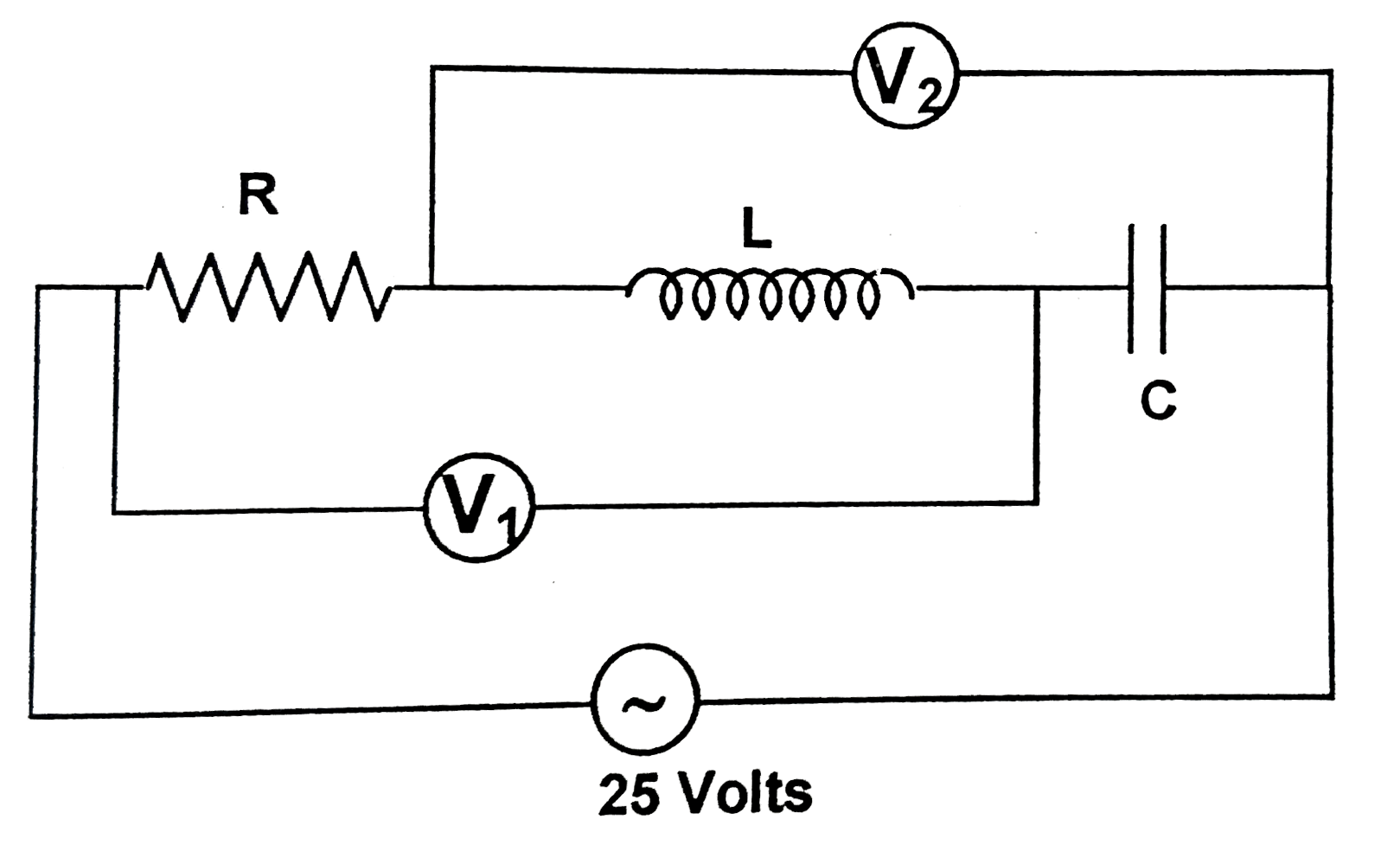
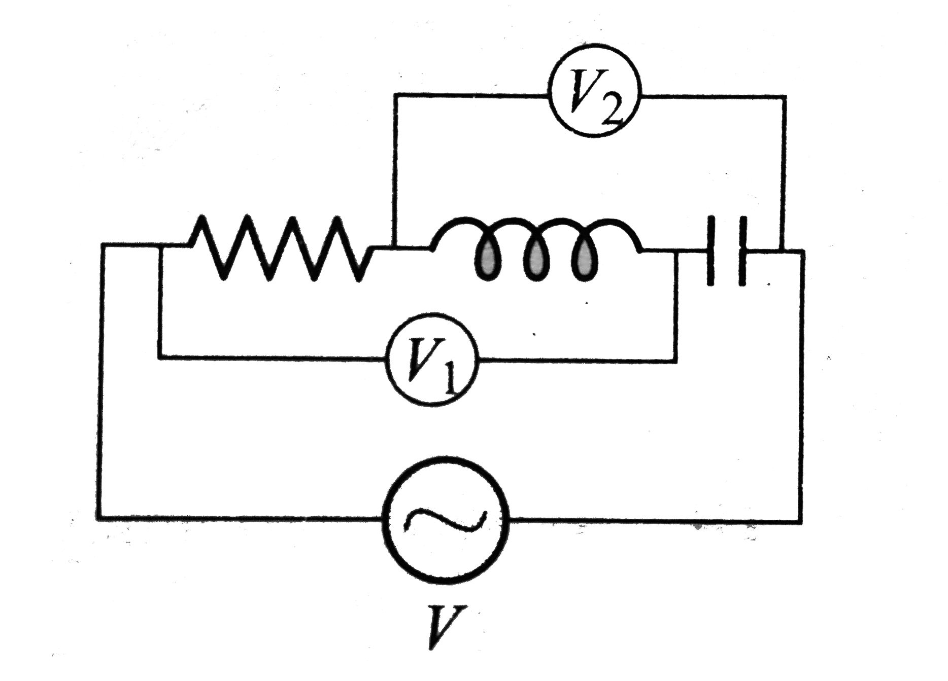
In an LCR series circuit, the reading of ideal voltmeters V1 and V2 are 20√2 volt and 15 volts respectively as shown in the figure (the given circuit in inductive in nature). Then
The voltage across resistor is 20 volts
The voltage across inductor is 20 volts
The voltage across capacitor is 5 volts
The power factor of the circuit is 45
The correct Answer is:A, B, C, D
V2R+V2L=V21=(20√2)2=800……(i)
VL−VC=15 …………….(ii)
√V2R+(VL−VC)2=(25)2
V2R+225=625
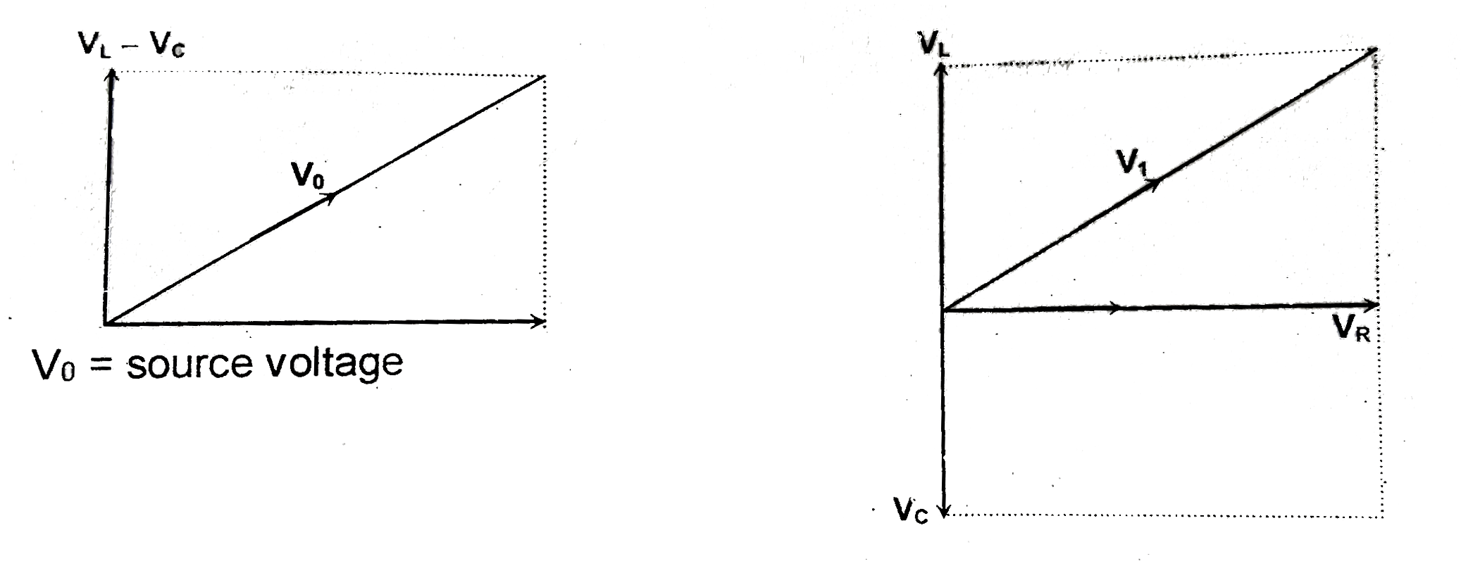
V0= source voltage
⇒VR=20 volts
VL=20 volts
VL−VC=15
20−VC=15
VC=5 volts
Power factor =cosϕ=R2=iRiZ=VRVZ=2025=45
Topper's Solved these Questions
- BOOK - FIITJEECHAPTER - TEST PAPERSEXERCISE - PHYSICS747videos
TEST PAPERS
- BOOK - FIITJEECHAPTER - SIMPLE HARMONIC MOTIONEXERCISE - Assignment Problems (Objective) (Level-II)20videos
SIMPLE HARMONIC MOTION
- BOOK - FIITJEECHAPTER - WORK, ENERGY AND POWER EXERCISE - COMPREHENSIONS ( Comprehension-II)5videos
WORK, ENERGY AND POWER
Similar Questions
Knowledge Check
- Question 1 - Select One
In the given circuit the readings of the voltmeter V1 and the ammeter A are
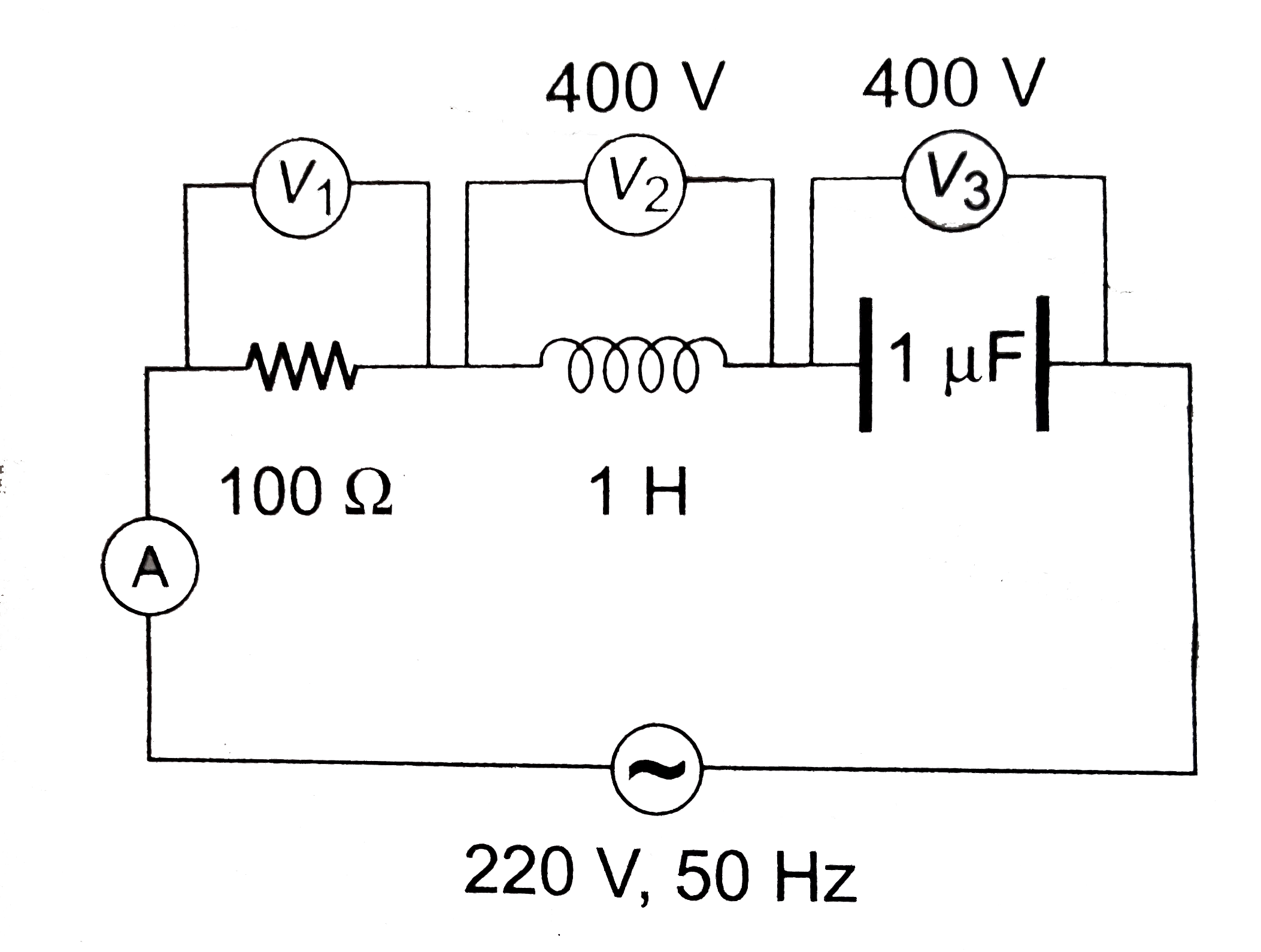 .A220V,2.2AB110V,1.1AC220V,1.1AD110V,2.2A
 - Question 2 - Select One or More
In a R−L−C series circuit shown in readings of voltmeters V1 and V2 are 100V and 120V.
Choose the corredct statement(s).
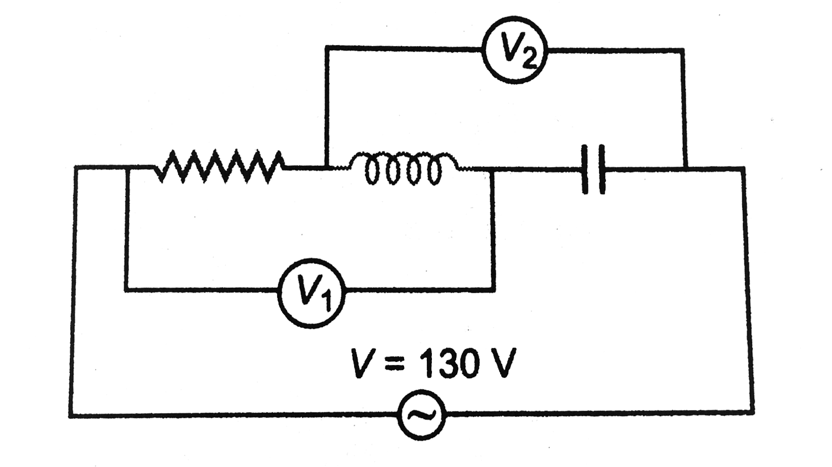 .AVoltage across resistor, inductor and capacitor are 50V,86.6V and 206.6V respectivelyBVoltage across resistor, inductor and capacitor are 10V,90V and 30V respectivelyCPower factor of the circuit is 513DCircuit is capacitive in nature
 - Question 3 - Select One
For the AC circuit shown, the reading of ammeter and voltmeter are 5A and 50√5 volts respectively, then
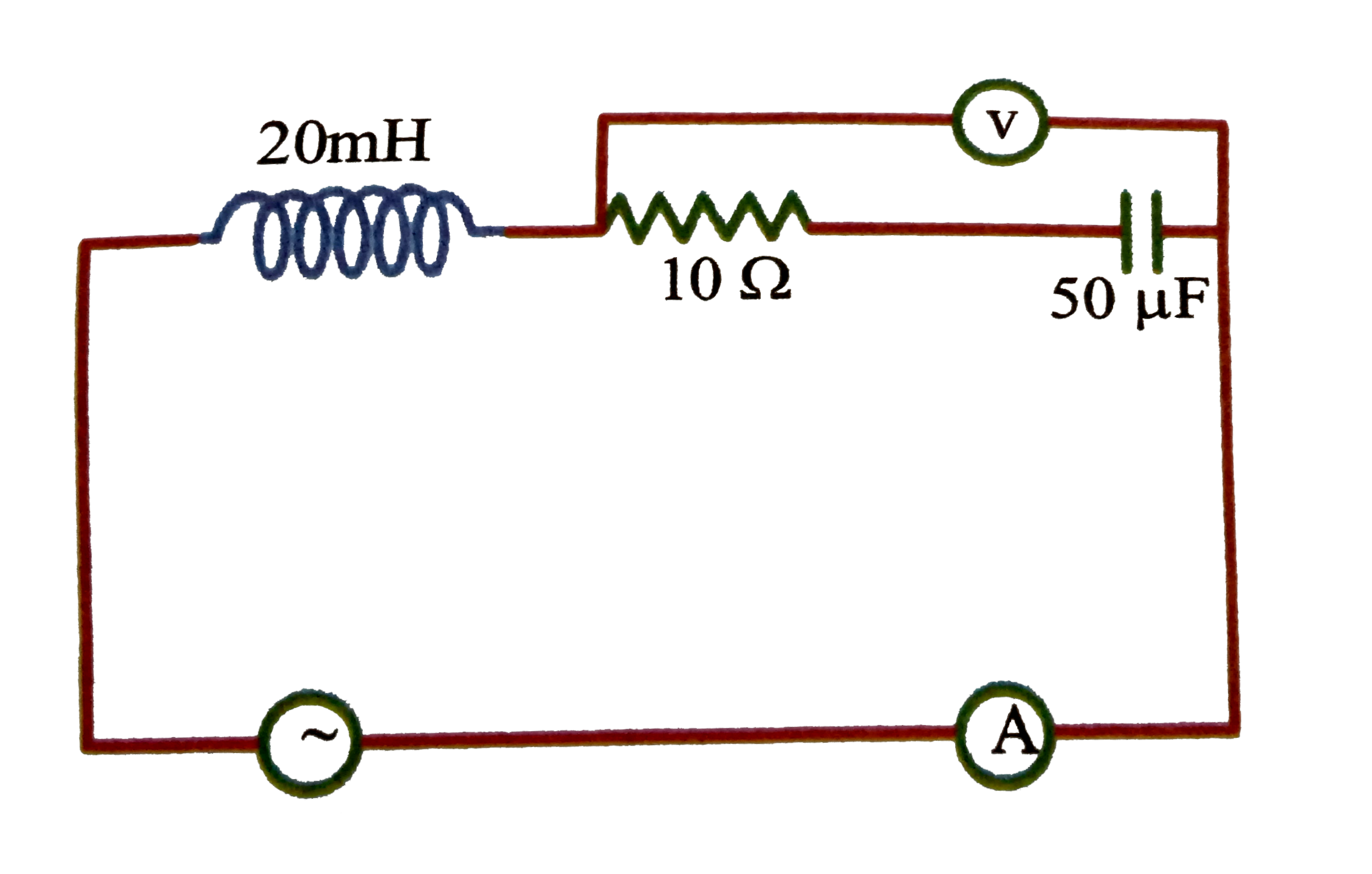 Aaverage power deliverd by the source is 250WBrms value of AC source is 50 voltsCvoltage gain is 2Dfrequency of ac source is 1000rad/s
In the following circuit reading of voltmeter V is
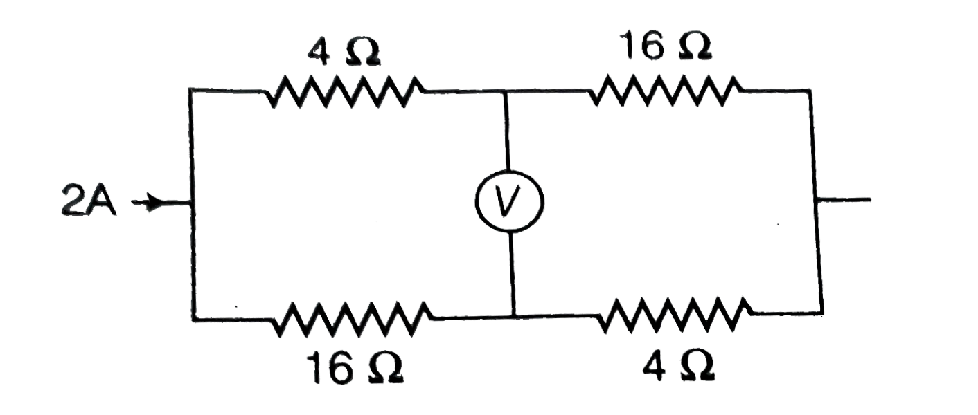 View Solution
In an RLC series circuit shown in fig. the reading of voltmeters (V1)and(V2) are 100 V and 200 V respectively. The source voltage is 130 V. for this situation, mark out the correct statements (s).
 View Solution
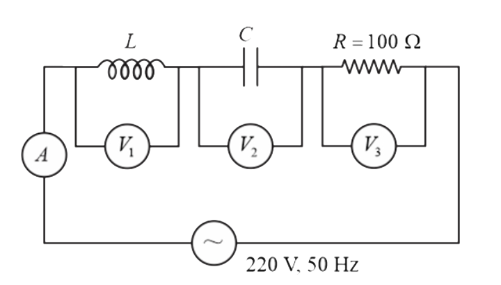
In the given circuit the reading of voltmeters V1andV2 are 300 volt each . The reading of the voltmeter V3 and ammeter A are respectively
 View Solution
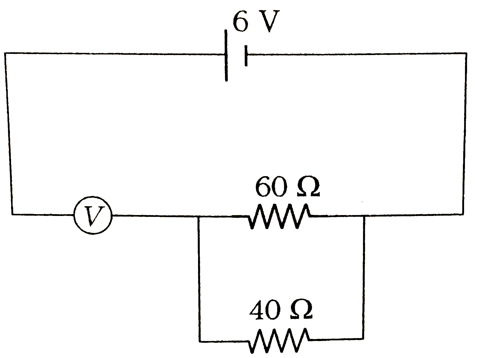
In the circuit shown in the figure, the voltmeter reading is
 View Solution
Consider the circuit shown in the figure, the cell is ideal. The readings of the ideal voltmeters V1 and V2 in volts are respectively.
 View Solution


