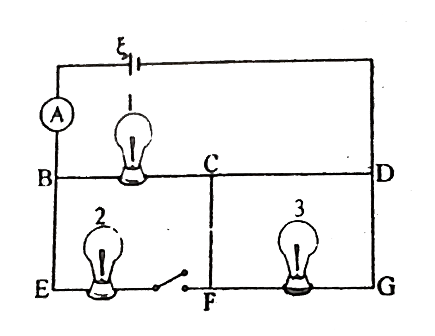
For the circuit shown, the ammeter reading is initially I. The switch in the circuit then is closed. Consequently (Battery and ammeter are ideal)
A
the ammeter reading decreases
B
the potential difference between E and F increases
C
the potential difference between E and F stays the same
D
bulb 3 lights up more brightly.
Text Solution
The correct Answer is:C
Since FCD shorts bulb 3, the circuit I equivalently wires BC and EF in parallel. As the voltage across each branch must be equal to the voltage of the battery, the voltage from E to F is unchanged by closing the switch. Initially, there is voltage across the switch and after it is closed, the voltage is across the resistor. By closing the switch, the current in the circuit increases as effective resistance a cross battery decreases. (across battery effective resistance =R11+(R1/R2)<R1 and the power from the battery must increase.
|
Topper's Solved these Questions
- MASTER PRACTICE PROBLEMBOOK - BANSALCHAPTER - MASTER PRACTICE PROBLEMEXERCISE - Subjective
107 Videos
- MASTER PRACTICE PROBLEMBOOK - BANSALCHAPTER - MASTER PRACTICE PROBLEMEXERCISE - Additional topic
70 Videos
- MASTER PRACTICE PROBLEMBOOK - BANSALCHAPTER - MASTER PRACTICE PROBLEMEXERCISE - Reasoning
75 Videos
- FLUID MECHANICSBOOK - BANSALCHAPTER - FLUID MECHANICSEXERCISE - PYQS AIEEE
10 Videos
- SEMICONDUCTORSBOOK - BANSALCHAPTER - SEMICONDUCTORSEXERCISE - CBSE Question
32 Videos
Similar Questions
Knowledge Check
In the circuit shown, the reading of ammeter is:
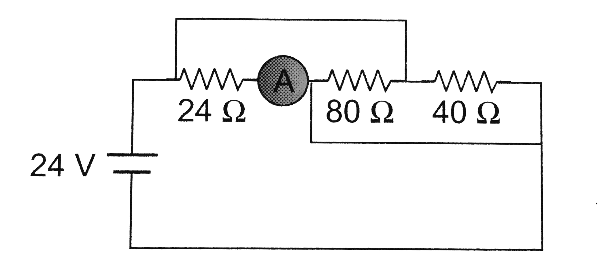 A0.2AB0.6AC2AD1A
In the circuit shown in figure, reading of ammeter will
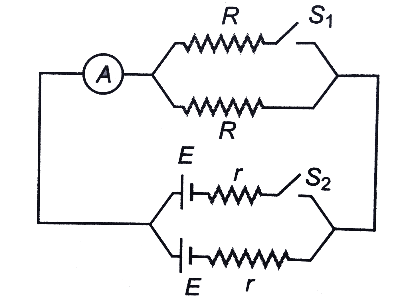 Ashows no deflection if S1 is closedBdecrease if S2 is closedCincrease if S2 is closedDdecrease if S2 is closed
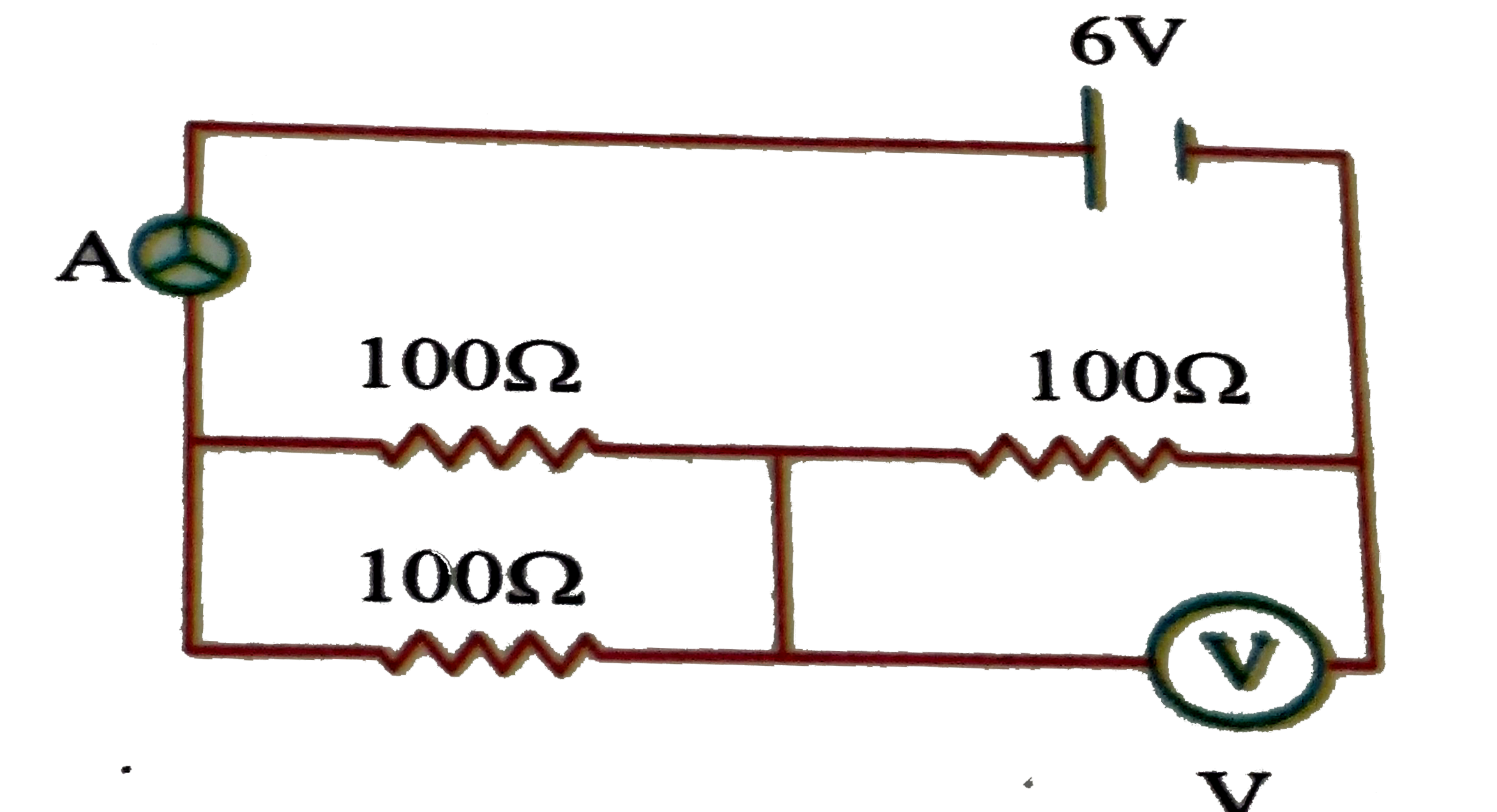
In the circuit shown, the reading of the voltmeter and the ammeter areA4V.0.2AB2V,0.4AC3V,0.6AD4V,0.04A
The ammeter reading in the given circuit is
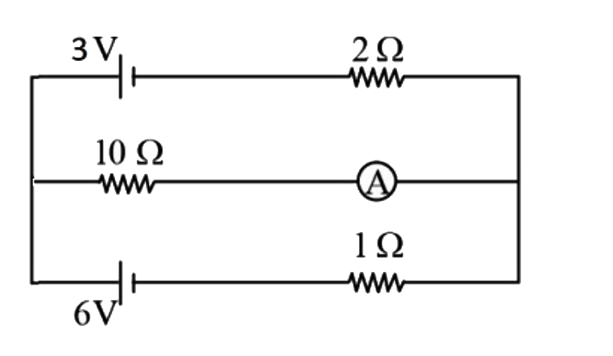
View SolutionThe reading of the ideal ammeter in the circuit is
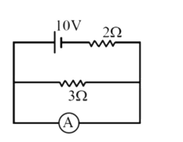
View SolutionThe reading of the ideal ammeter in the circuit is

View SolutionThe ammeter reading in the given circuit is

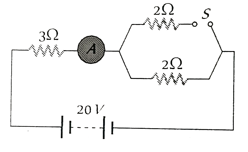
View SolutionIn the circuit shown, the reading of ammeter when switch S is open and when switch S is closed respectively are
View Solution

