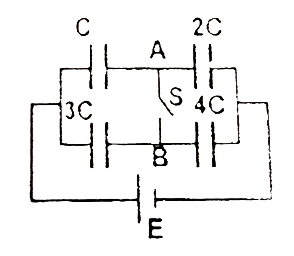
Four capacitors of capacitance C, 2C, 3C & 4C respectively are connected as shown in figure. Battery is deal and all the connected wires have no resistance capcitance or inductance. Initially the switch S is open. If at t=0 switch S is closed
Heat generated is the switch after closing switch is
CE2105
2CE2105
CE25
CE235
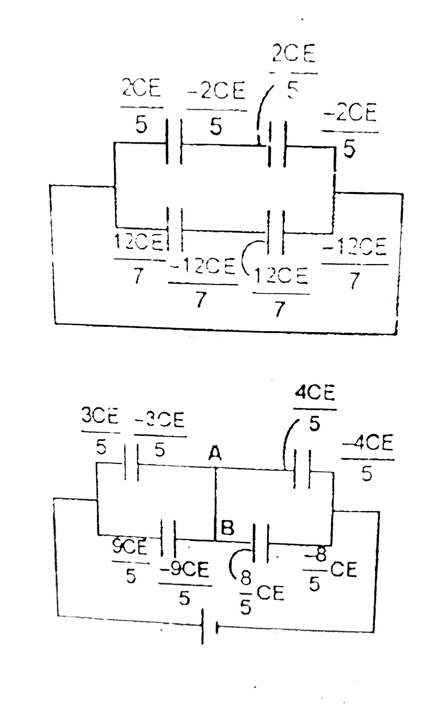
Initial and final charges on capacitors are shown in figure (a) and (b) respectively charge flown through AB is CE5 work done by battery
=Wb=(Qtake−Qtake)E
Heat produced =Wb−ΔU=CE2105J
Topper's Solved these Questions
- GMP ASSESMENTBOOK - FIITJEECHAPTER - GMP ASSESMENTEXERCISE - Numerical Based
61 Videos
- GMP ASSESMENTBOOK - FIITJEECHAPTER - GMP ASSESMENTEXERCISE - Multiple Question
58 Videos
- GENERAL PHYSICSBOOK - FIITJEECHAPTER - GENERAL PHYSICSEXERCISE - MATRIX MATCH TYPE
3 Videos
- GRAVITATIONBOOK - FIITJEECHAPTER - GRAVITATIONEXERCISE - Numerical based Question
2 Videos
Similar Questions
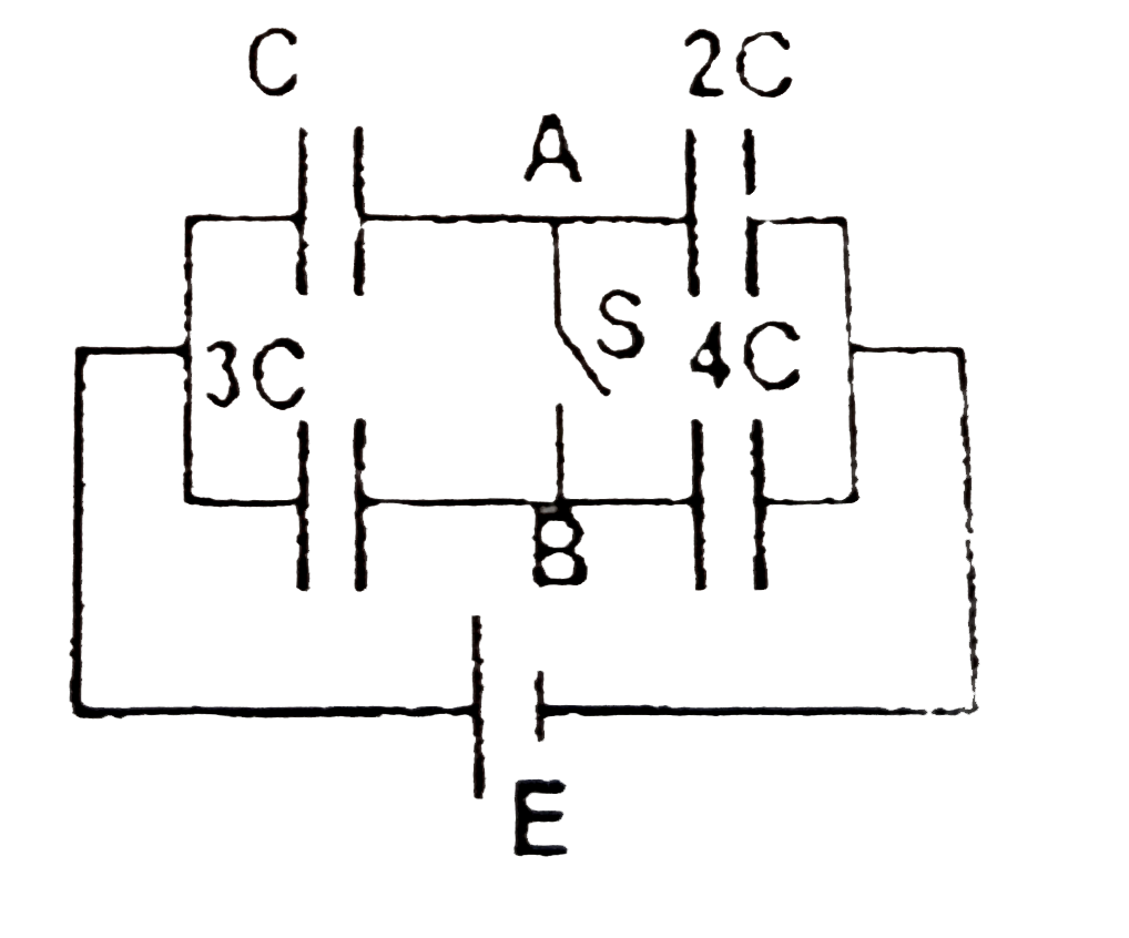
Four capacitors of capacitance C, 2C, 3C & 4C respectively are connected as shown in figure. Battery is deal and all the connected wires have no resistance capcitance or inductance. Initially the switch S is open. If at t=0 switch S is closed
The work done by battery after closing, switch is
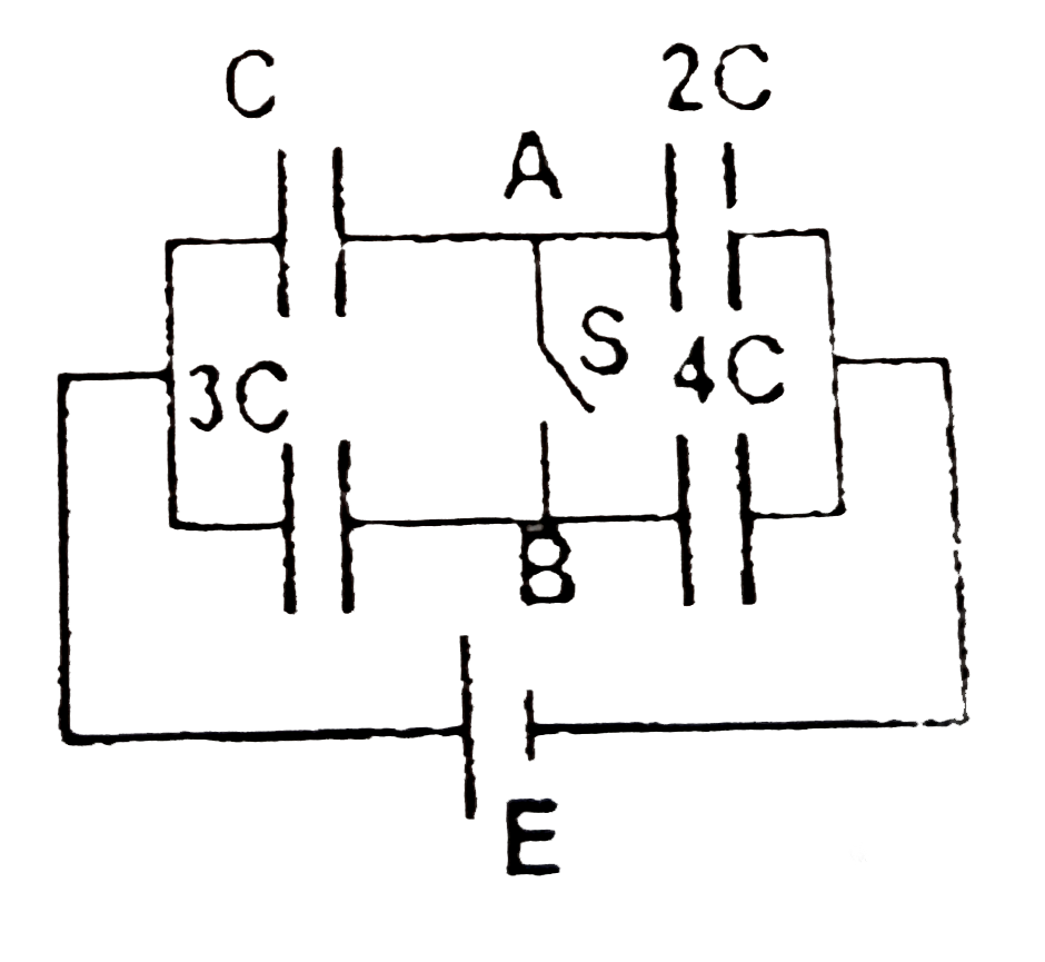
View SolutionFour capacitors of capacitance C, 2C, 3C & 4C respectively are connected as shown in figure. Battery is ideal and all the connected wires have no resistance capcitance or inductance. Initially the switch S is open. If at t=0 switch S is closed
The charge flown through connector AB after switch is closed is
View Solution
Knowledge Check
Four capacitors of capacitance C, 2C, 3C & 4C respectively are connected as shown in figure. Battery is deal and all the connected wires have no resistance capcitance or inductance. Initially the switch S is open. If at t=0 switch S is closed
The work done by battery after closing, switch is
 ACE25B2CE2105CCE2105DCE235
Four capacitors of capacitance C, 2C, 3C & 4C respectively are connected as shown in figure. Battery is deal and all the connected wires have no resistance capcitance or inductance. Initially the switch S is open. If at t=0 switch S is closed
The charge flown through connector AB after switch is closed is
 ACEBCE2CCE5DCE3
When the switch S is closed at t=0, identify the correct statement just after closing the switch as shown in figure
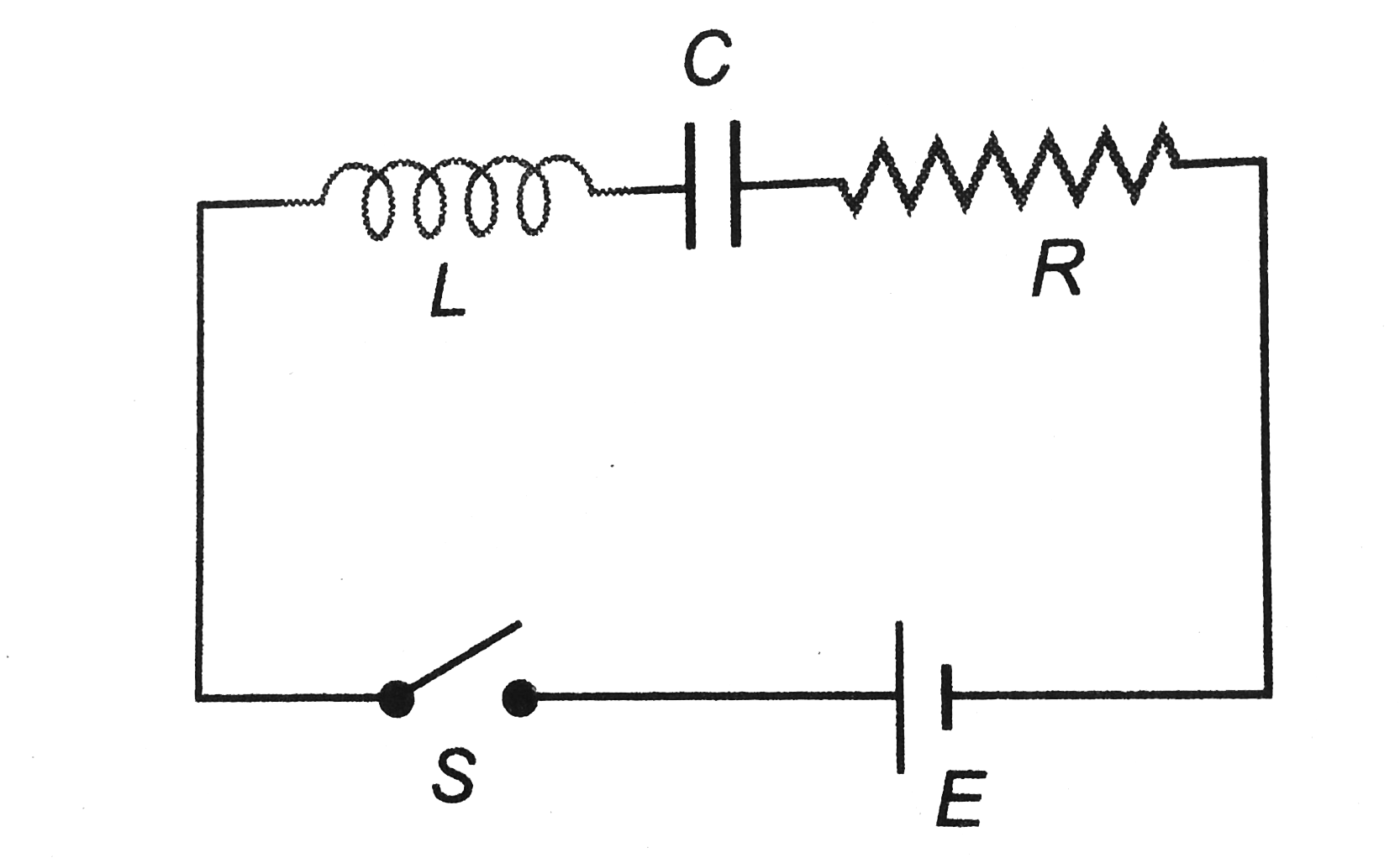 Athe current in the circuit is maximumBequal and opposite voltages are dropped across inductor and resistorCthe entire voltage is dropped across inductorDAll of the above
shows three resistances are
connected with switch S initially the switch is open. When
the switch S is closed find the current passed through it.
View Solutionshows three resistances are
connected with switch S initially the switch is open. When
the switch S is closed find the current passed through it.
View SolutionIn the circuit shown in figure the switch S is closed at t = 0. A long time after closing the switch
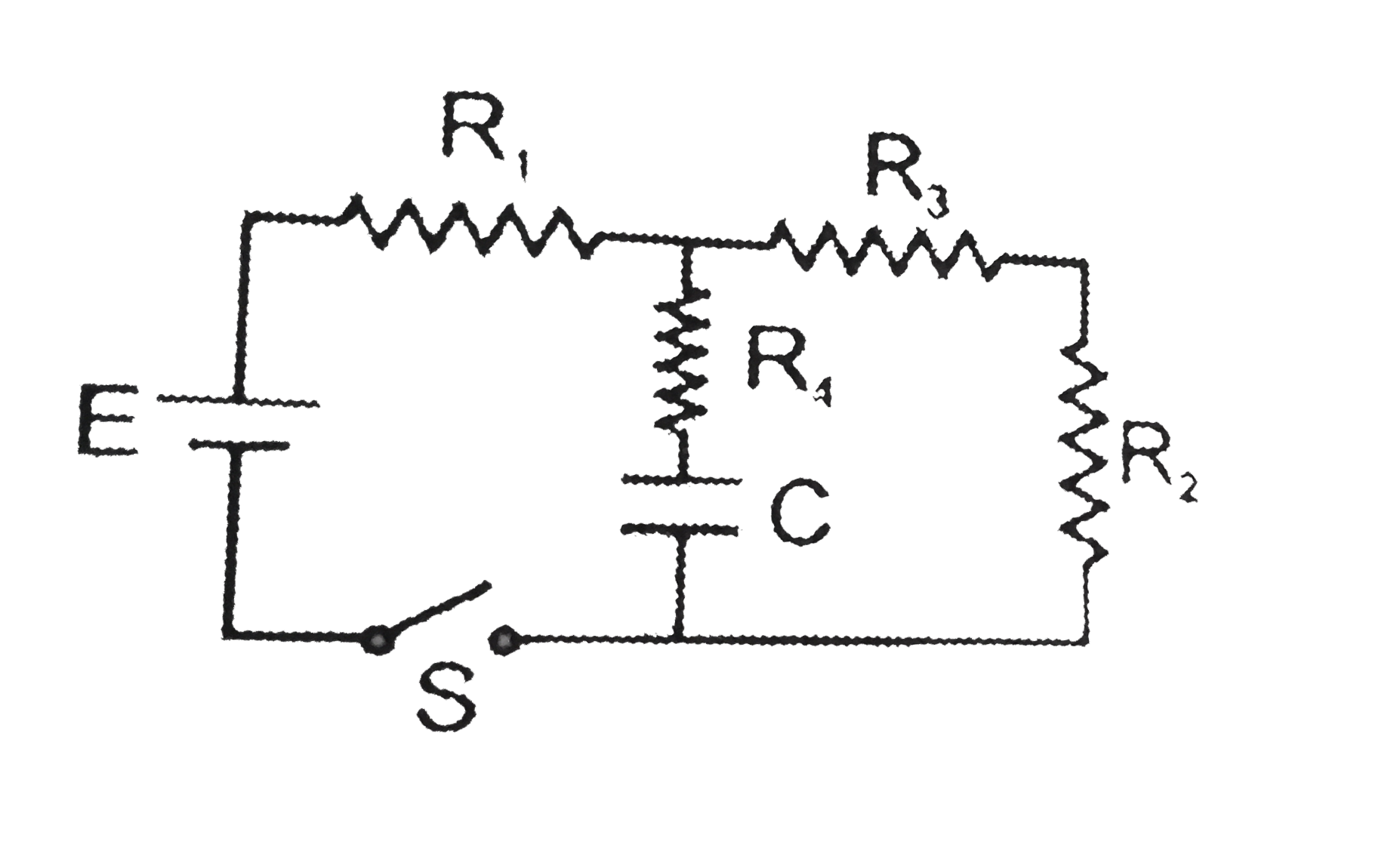
View SolutionWhen the switch S is closed at t=0, identify the correct statement just after closing the switch as shown in figure

View SolutionAn inductor L and a resistance R are connected in series with a battery of emf E and a switch. Initially the switch is open. The switch is closed at an instant t = 0. Select the correct alternatives
View Solution
