An inductor L and a resistance R are connected in series with a battery of emf E and a switch. Initially the switch is open. The switch is closed at an instant t = 0. Select the correct alternatives
At t = 0, induced emf in inductor is zero
At , energy stored in the inductor is
At , induced emf in the inductor is
At , voltage drop across the resistor is
The correct Answer is:B, C, D
To solve the problem regarding the LR circuit connected to a battery, we will analyze the behavior of the circuit when the switch is closed at t=0. We will derive the current, induced EMF, energy stored in the inductor, and the voltage drop across the resistor step by step.
Step 1: Understanding the Circuit
When the switch is closed at t=0, the circuit consists of an inductor L, a resistor R, and a battery of EMF E. Initially, the current in the circuit is zero because the switch was open.
Step 2: Current in the Circuit
The current I(t) in the circuit as a function of time t can be expressed using the formula:
I(t)=ER(1−e−RLt)
At t=0:
I(0)=ER(1−e0)=0
This means that initially, the current is zero.
Step 3: Induced EMF in the Inductor
The induced EMF E in the inductor can be calculated using:
E=−LdIdt
Differentiating I(t):
dIdt=ER⋅RLe−RLt=ELe−RLt
Thus,
E=−L⋅ELe−RLt=−Ee−RLt
At t=0:
E(0)=−E⋅e0=−E
This indicates that the induced EMF is equal to −E at t=0.
Step 4: Energy Stored in the Inductor
The energy U stored in the inductor at time t is given by:
U=12LI2
At t=LR:
I(LR)=ER(1−e−1)
Substituting this into the energy formula:
U=12L(ER(1−1e))2
Calculating this gives:
U=LE22R2(1−1e)2
Step 5: Voltage Drop Across the Resistor
The voltage drop VR across the resistor can be calculated using Ohm's law:
VR=I⋅R
At t=LR:
VR=(ER(1−1e))R=E(1−1e)
Summary of Results
1. At t=0, the induced EMF in the inductor is −E (not zero).
2. At t=LR, the energy stored in the inductor is LE22R2(1−1e)2 (true statement).
3. At t=LR, the induced EMF is E/e (true statement).
4. The voltage drop across the resistor is E(1−1e) (this option is incorrect).
When the switch is closed at t=0, the circuit consists of an inductor L, a resistor R, and a battery of EMF E. Initially, the current in the circuit is zero because the switch was open.
The current I(t) in the circuit as a function of time t can be expressed using the formula:
I(t)=ER(1−e−RLt)
At t=0:
I(0)=ER(1−e0)=0
This means that initially, the current is zero.
The induced EMF E in the inductor can be calculated using:
E=−LdIdt
Differentiating I(t):
dIdt=ER⋅RLe−RLt=ELe−RLt
Thus,
E=−L⋅ELe−RLt=−Ee−RLt
At t=0:
E(0)=−E⋅e0=−E
This indicates that the induced EMF is equal to −E at t=0.
The energy U stored in the inductor at time t is given by:
U=12LI2
At t=LR:
I(LR)=ER(1−e−1)
Substituting this into the energy formula:
U=12L(ER(1−1e))2
Calculating this gives:
U=LE22R2(1−1e)2
The voltage drop VR across the resistor can be calculated using Ohm's law:
VR=I⋅R
At t=LR:
VR=(ER(1−1e))R=E(1−1e)
1. At t=0, the induced EMF in the inductor is −E (not zero).
2. At t=LR, the energy stored in the inductor is LE22R2(1−1e)2 (true statement).
3. At t=LR, the induced EMF is E/e (true statement).
4. The voltage drop across the resistor is E(1−1e) (this option is incorrect).
Topper's Solved these Questions
- ELECTROMAGNETIC INDUCTIONBOOK - AAKASH INSTITUTE ENGLISHCHAPTER - ELECTROMAGNETIC INDUCTIONEXERCISE - Assignment (SECTION - D)
6 Videos
- ELECTROMAGNETIC INDUCTIONBOOK - AAKASH INSTITUTE ENGLISHCHAPTER - ELECTROMAGNETIC INDUCTIONEXERCISE - Assignment (SECTION - E)
8 Videos
- ELECTROMAGNETIC INDUCTIONBOOK - AAKASH INSTITUTE ENGLISHCHAPTER - ELECTROMAGNETIC INDUCTIONEXERCISE - Assignment (SECTION - B)
22 Videos
- ELECTRIC CHARGES AND FIELDS BOOK - AAKASH INSTITUTE ENGLISHCHAPTER - ELECTRIC CHARGES AND FIELDS EXERCISE - comprehension
3 Videos
- ELECTROMAGNETIC WAVESBOOK - AAKASH INSTITUTE ENGLISHCHAPTER - ELECTROMAGNETIC WAVESEXERCISE - ASSIGNMENT SECTION - D Assertion-Reason Type Questions
25 Videos
Similar Questions
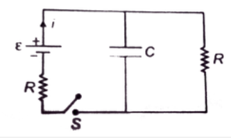
In the circuit shown, the switch is closed at t=0. Select the correct alternative(s)

View SolutionAn inductor of inductance L = 8 H and a resistor of resistance R = 2Ω are connected in series with a battery of emf E = 10 V as shown in the figure. If the switch is closed at t = 0, then the voltage drop across the inductor at t = 1 s will be in volts)
View Solution
Knowledge Check
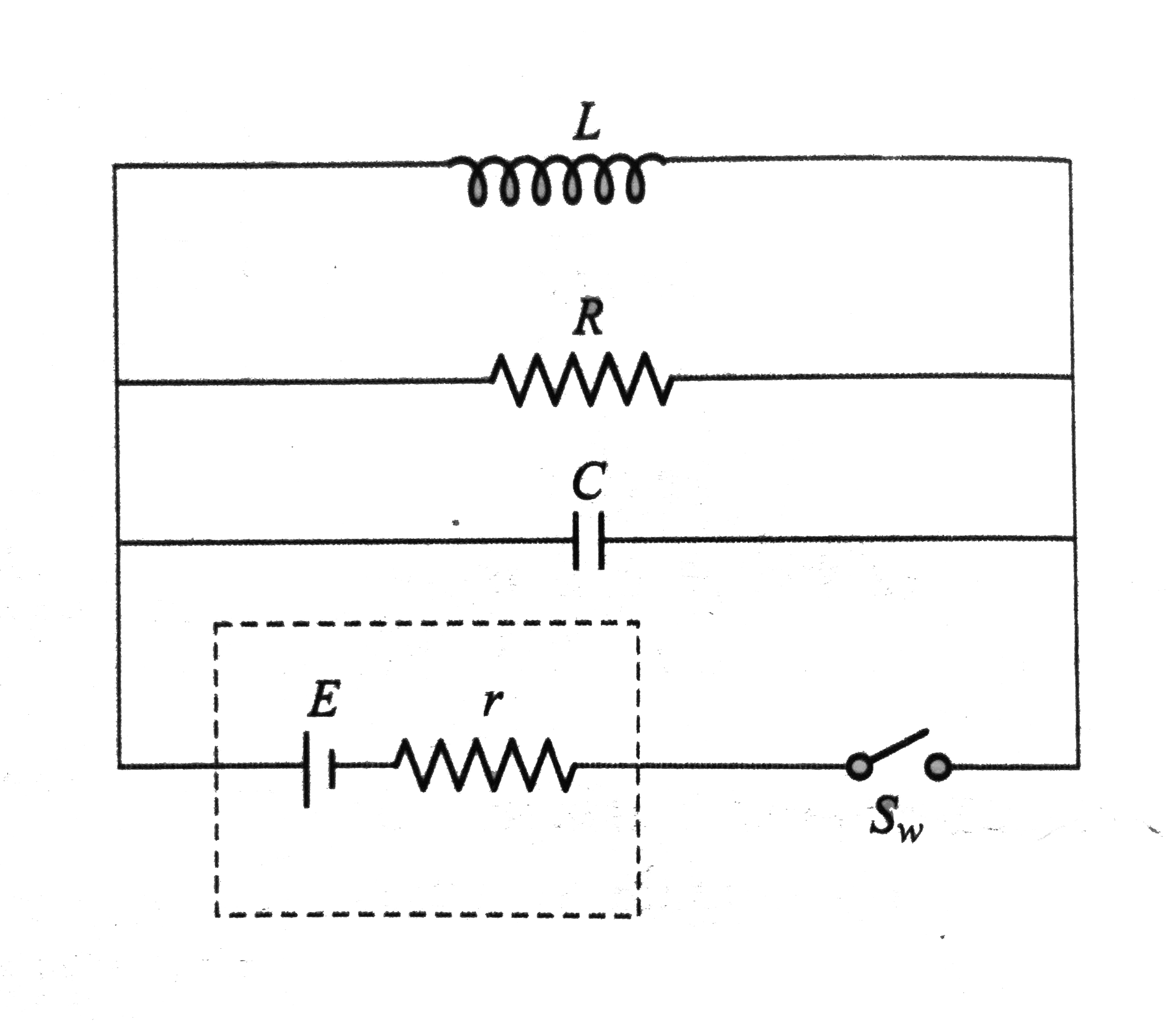
A pure inductor L, a capactior C and a resistance R are connected across a battery of emf E and internal resistance r as shows in Fig. Switch SW is closed at t=0, select the correct altermative (S).
 ACurrent through resistance R is zero all the time.BCurrent through resistance R is zero at t = 0 and t→∞.CMaximum charge stored in the capacitor is Cε.DMaximum energy stored in the inductor is equal to the maximum energy stored in the capacitor.
An inductor L and a resistor R are connected in series to a battery, through a key/switch. Show graphically, how current decreases with time when the key/switch is opened.
View Solutionshows three resistances are
connected with switch S initially the switch is open. When
the switch S is closed find the current passed through it.
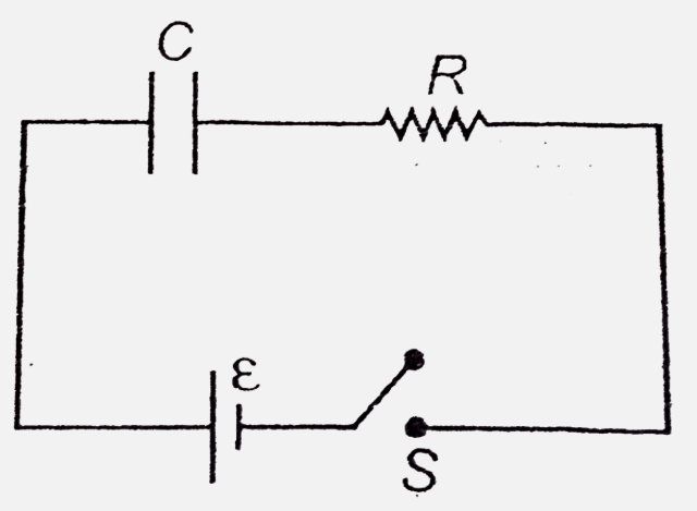
View SolutionAn uncharged capacitor is connected to an ideal battery through a resistance R and a switch S. Initially the switch is open . At an instant, the switch is closed . Taking this instant as t=0, which of the following graphs represent correct variation of the quantity taken along y -axis with time ?

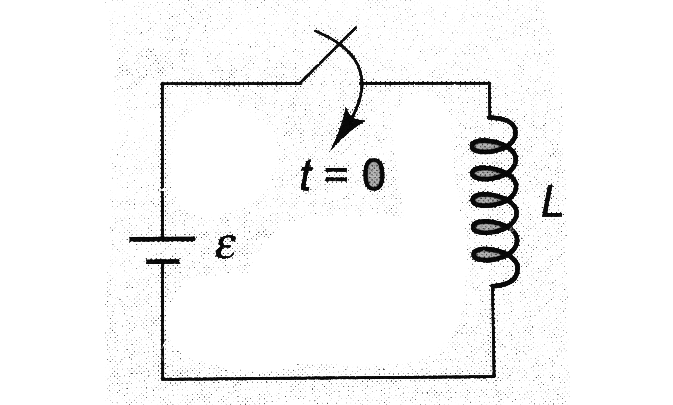
View SolutionA circuit contains an ideal cell and an inductor with a switch. Initially, the switch is open. It is closed at t=0. Find the current as a function of time.

View SolutionA circuit contains an ideal cell and an inductor with a switch. Initially, the switch is open. It is closed at t=0. Find the current as a function of time.

View SolutionSwitch is closed at t=0 then the current in the circuit at t=L2R is
_PHY_E06_157_Q01.png)
View SolutionA solenoid L and a resistor R are connected in series to a battery, through a switch. When the switch is put on, current I flowing through it varies with time t as shown in which of the graphs given below :∗
View Solution
