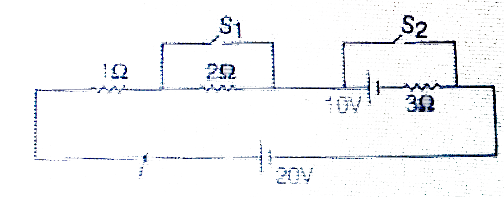
In the circuit shown in the adjacent figure
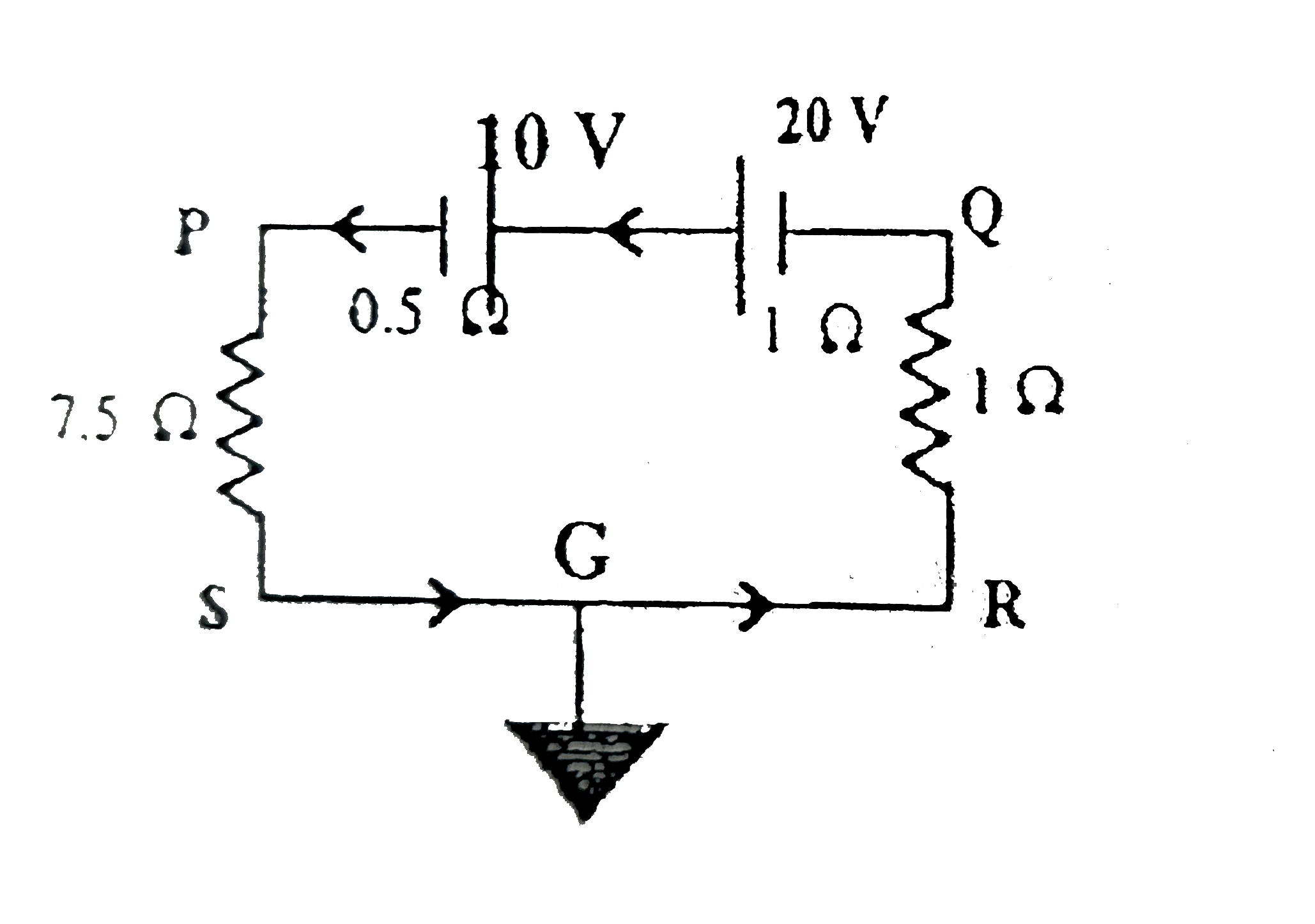
A
the potential at P is −7.5V
B
the potential at Q is −1V
C
the potential at R is zero
D
the potential at S is zero
Video Solution
Text Solution
The current in the circuit I=(20−10)(7.5+.5+1+1)=1010=1Amp
The potential difference across PSVPS=7.5×1=7.5V
The potential difference across QR, VQR=1×1=1V
As point G is connected to earth hence potentials of R and S is zero.
The direction of the current in the circuit is from P to S, hence point P is at higher potential.
∴Vp=7.5V
similarly VQ=−1V
|
Topper's Solved these Questions
- CURRENT ELECTRICITYBOOK - FIITJEECHAPTER - CURRENT ELECTRICITYEXERCISE - Illustration
10 Videos
- CURRENT ELECTRICITYBOOK - FIITJEECHAPTER - CURRENT ELECTRICITYEXERCISE - SOLVED PROBLEMS (SUBJECTIVE)
10 Videos
- COLLISION BOOK - FIITJEECHAPTER - COLLISION EXERCISE - (NUMERICAL BASED QUESTIONS)
4 Videos
- ELASTICITY AND WAVES BOOK - FIITJEECHAPTER - ELASTICITY AND WAVES EXERCISE - Assignment Problems (Objective) Level-II
15 Videos
Similar Questions
Knowledge Check
Which of the following statements is correct regarding the AC circuit shown in the adjacent figure?
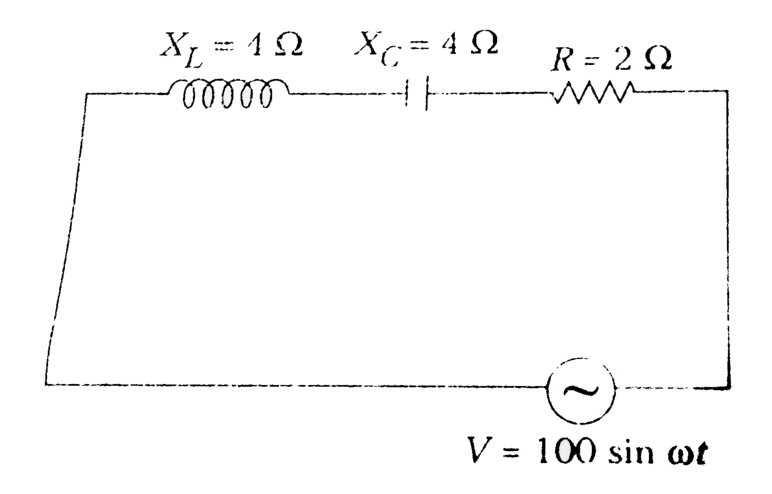 AThe rms value of current through the circuit is irms = 5√2 ABThe phase difference between source emf and current is = cos−1 (1/3)CAvereage power dissipated in the circuit is 500 WDNone of the above
In the circuit shown in figure
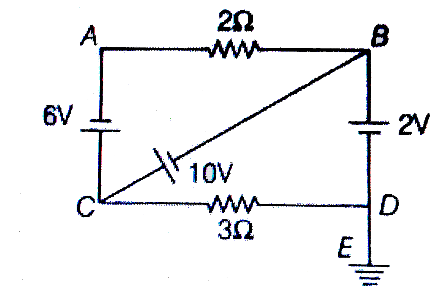 Acurrent passing through 2Ω resistance is 2 ABcurrent passing through 3Ω resistance is 4 ACcurrent in wire DE is zero.Dpotential of point A is 10 V
In the circuit shown in figure
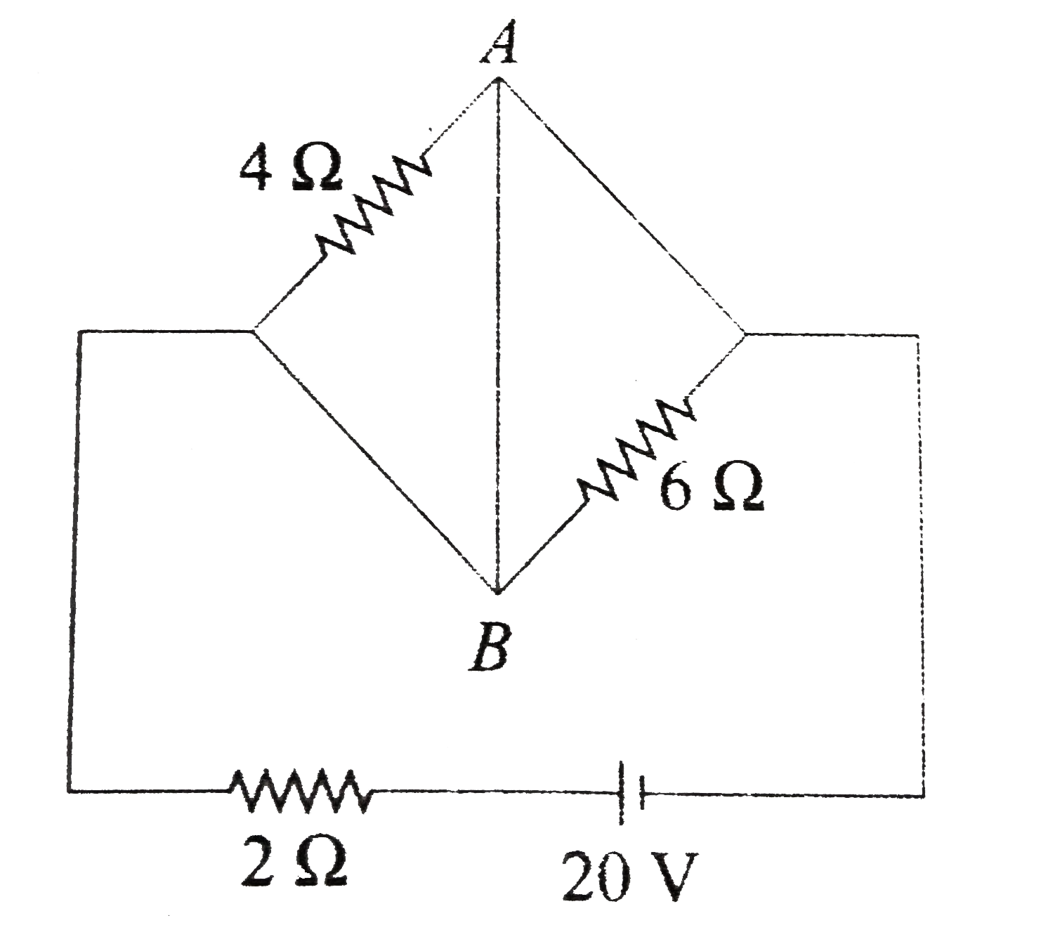
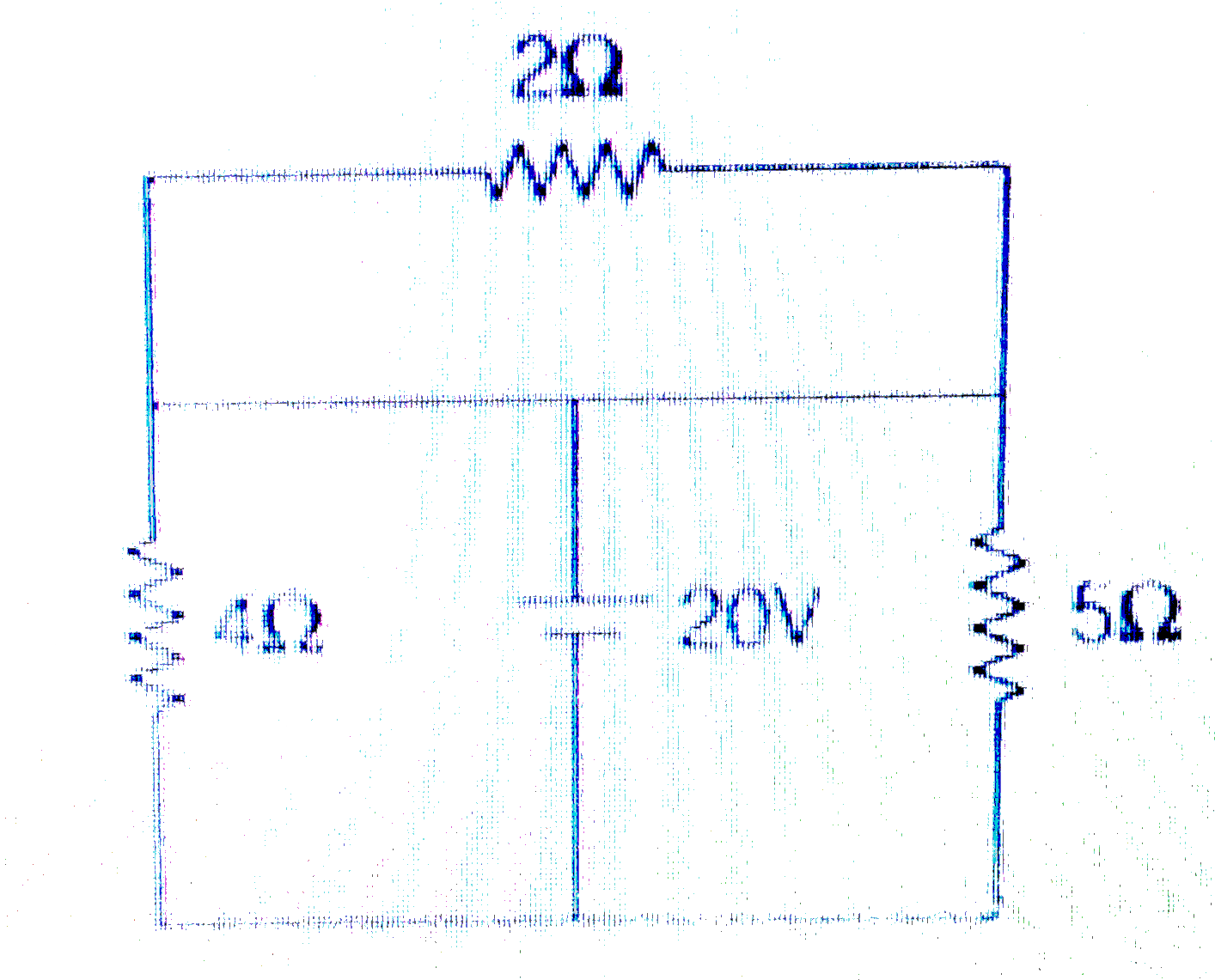 Acurrent passing through 2Ω resistance is zeroBcurrent passing through 4Ω resistance is 5 ACcurrent passing through 5Ω resistance is 4 ADAll of the above

_PHY_E05_104_Q01.png)
