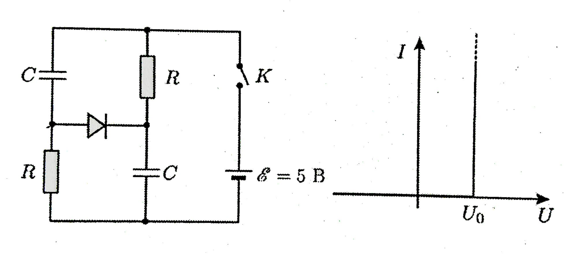
In the initial state of the circuit shown in the figure, the capacitors are not charged. At the time t=0 key is closed. Find the charge accumulated on the capacitor if R=10kΩ,C=10μF, and battery internal resistance r=10Ω. Volt-ampere characteristic of a diode is show in the chart, with U0=0.7V
The correct Answer is:q=CU=C(ε−U0)2=2.15×10⁻⁶
Topper's Solved these Questions
- SEMICONDUCTORSBOOK - BANSALCHAPTER - SEMICONDUCTORSEXERCISE - Exercise-4
37 Videos
- SEMICONDUCTORSBOOK - BANSALCHAPTER - SEMICONDUCTORSEXERCISE - Exercise-4 Section-B
6 Videos
- SEMICONDUCTORSBOOK - BANSALCHAPTER - SEMICONDUCTORSEXERCISE - Exercise-2
24 Videos
- MASTER PRACTICE PROBLEMBOOK - BANSALCHAPTER - MASTER PRACTICE PROBLEMEXERCISE - Additional topic
70 Videos
- TEST PAPERSBOOK - BANSALCHAPTER - TEST PAPERSEXERCISE - PHYSICS PART C
14 Videos
Similar Questions
Knowledge Check
In the circuit shown in figure, charge on 10μF capacitor is given as
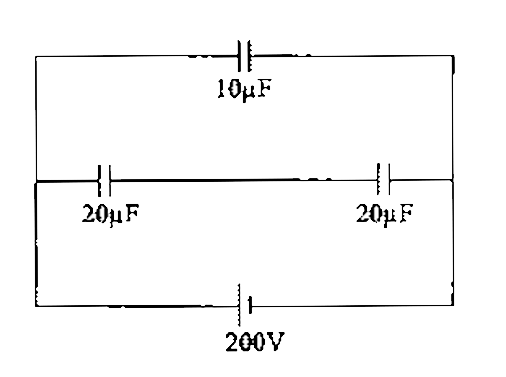 A2×10−3CB16×10−4CC4×10−3CD8×10−4C
In the circuit shown in figure, the capacitor is charged with a cell of 5V.If the switch is closed at t=0, then at t=12s, charge on the capacitor is
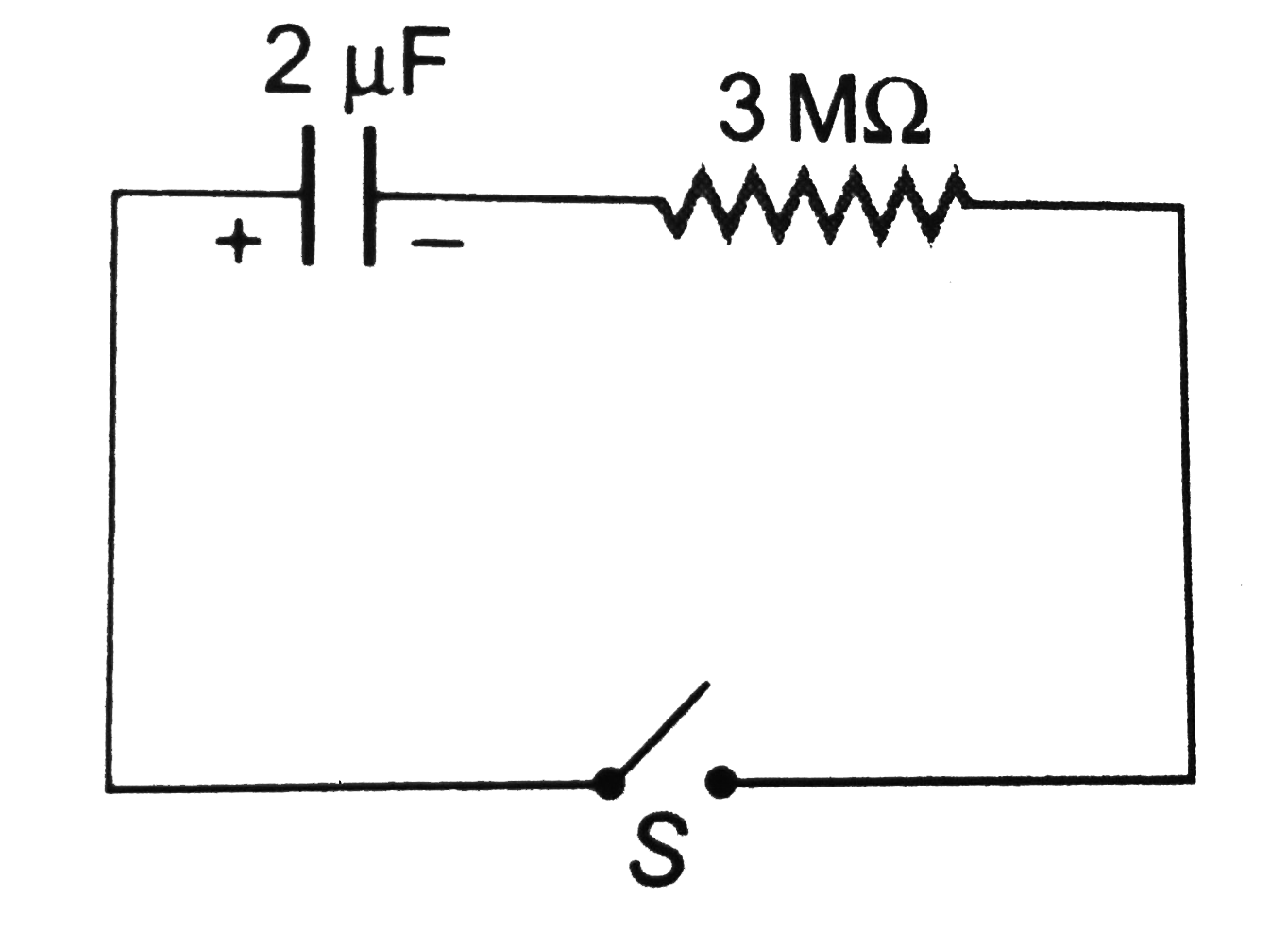 A(0.37)10μCB(0.37)210μCC(0.63)10μCD(0.63)210μC
In the circuit shown key is closed at t=0 with capacitor initially uncharged.
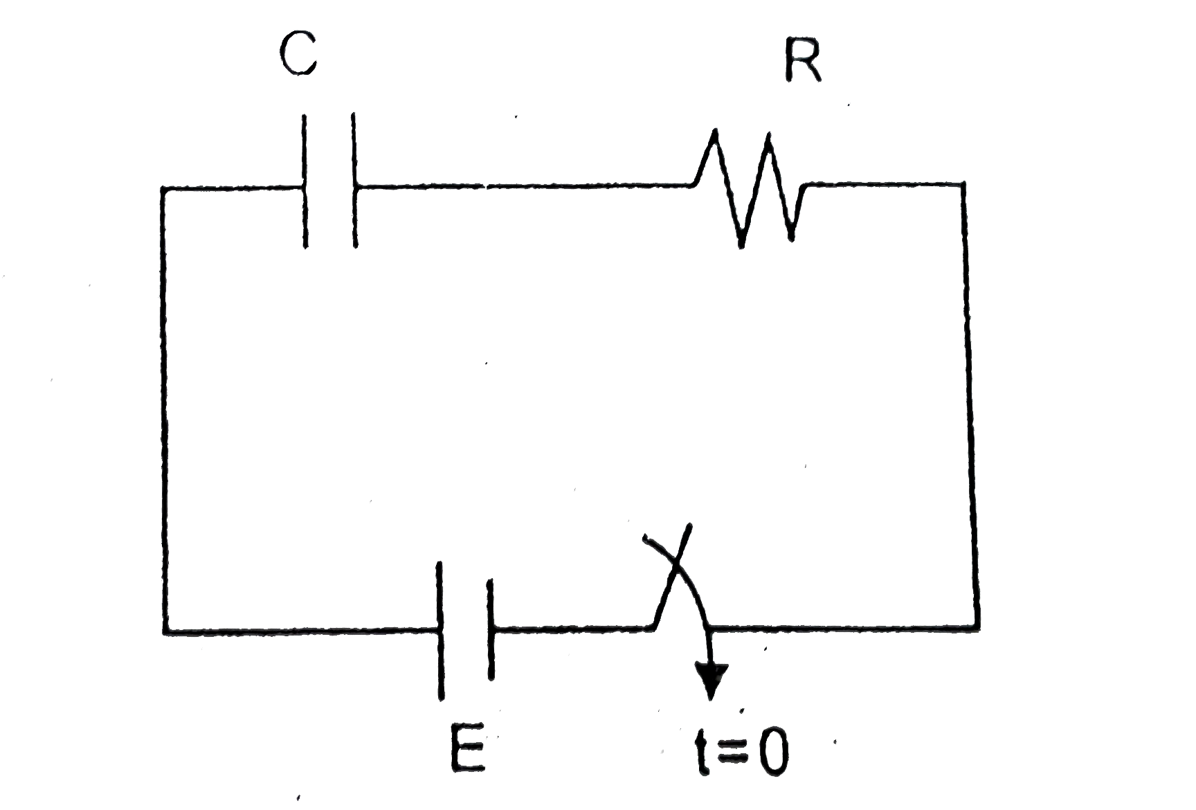 ARate of increase of capacitors energy, just after the switch is closed is E2RBMaximum power supplied by the cell is E2RCAt t=RCIn2, capacitor is charged up to half of the energy stored by it in steady stateDAt t=RCIn2, potential difference across capacitor is same that across resistor.
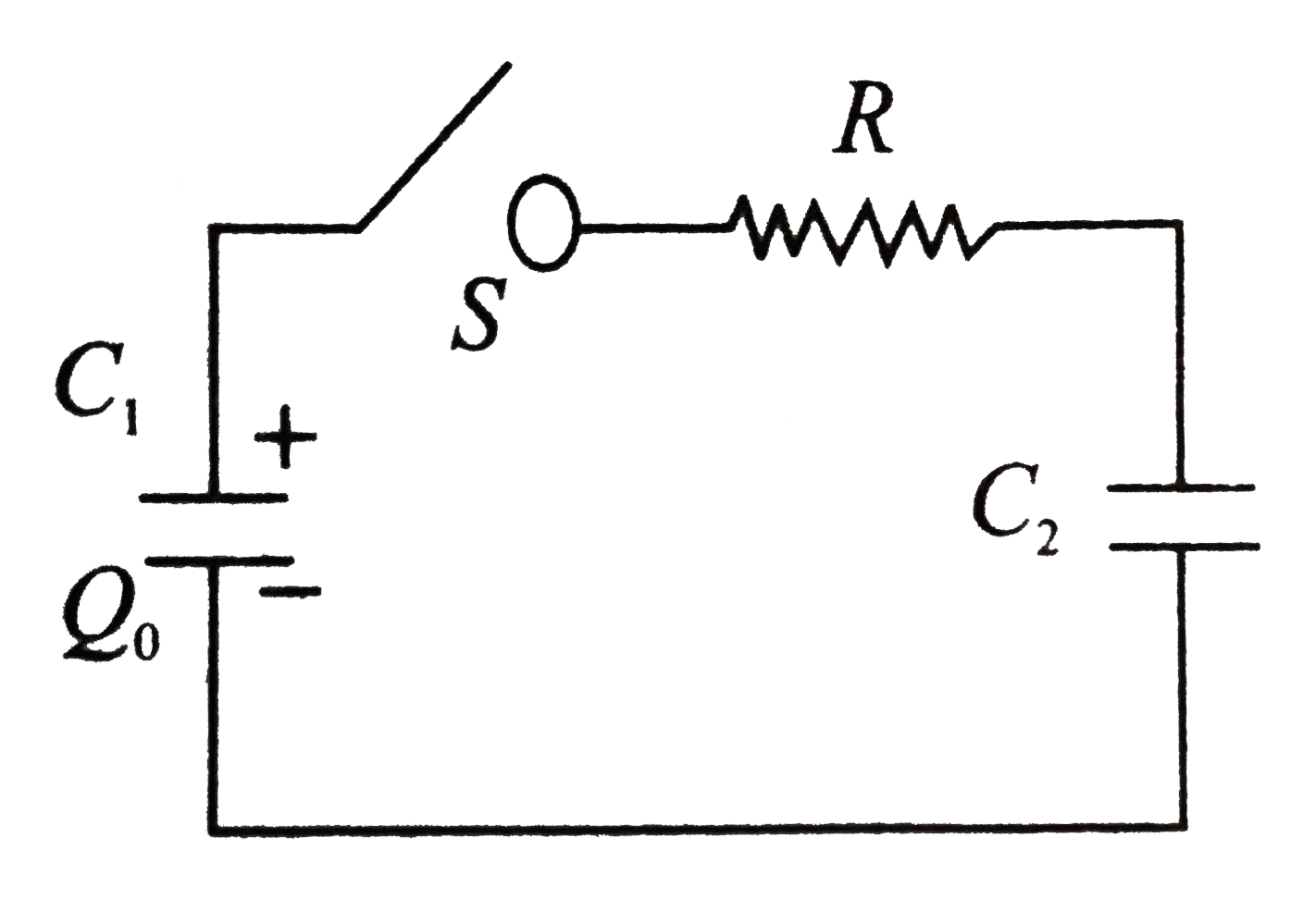
In the circuit shown, the capacitor C1 is initially charged with charge q0. The switch S is closed at time t = 0 . The charge on C2 after time t is
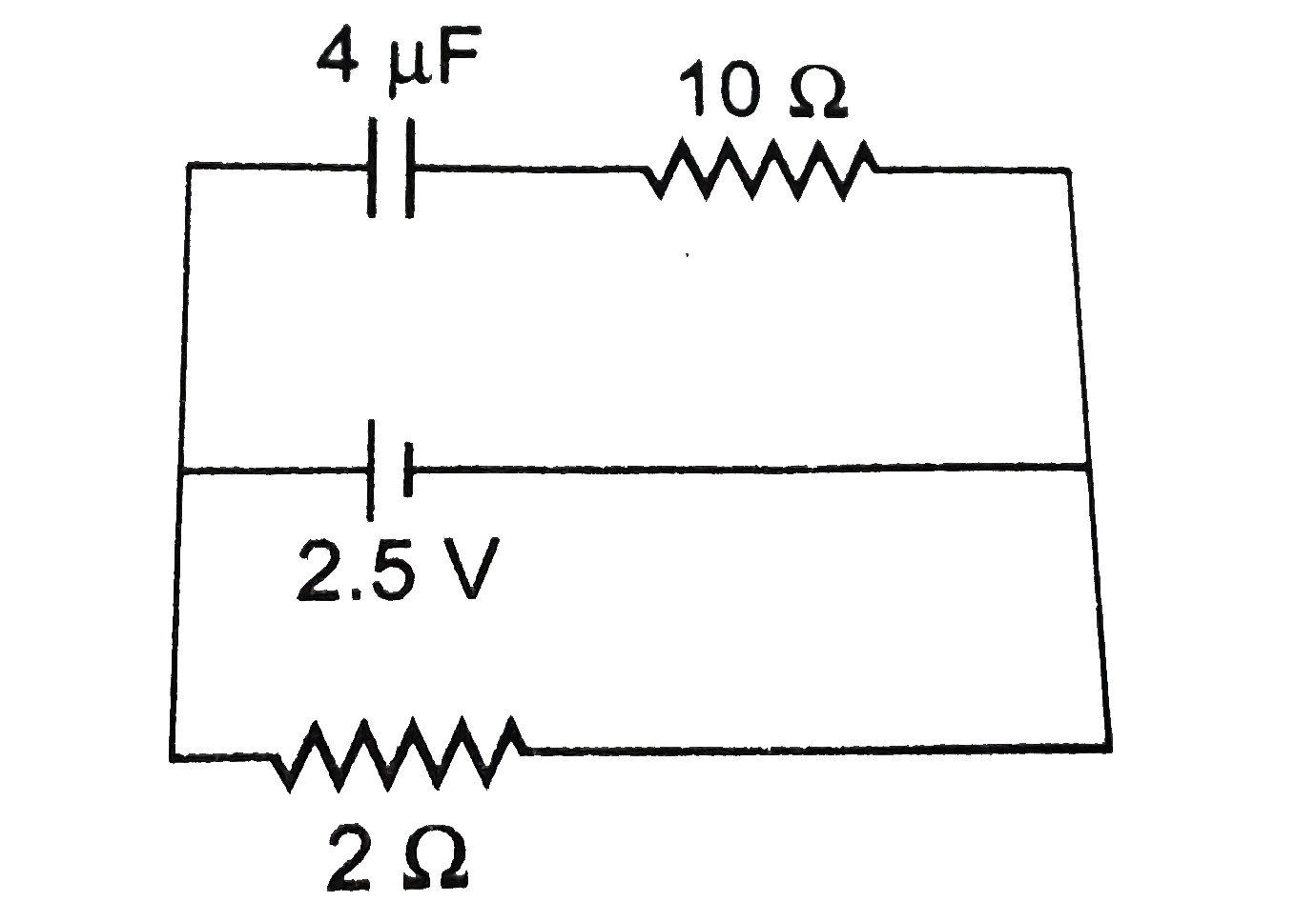
View SolutionA capacitor of 4μF is connected as shwon in the figure. The internal resistance of the battery is 0.5Ω. The amount of charge on the capacitor plates will be
View SolutionIn the circuit shown, the capacitor C1 is initially charged with charge q0. The switch S is closed at time t = 0 . The charge on C2 after time t is

View SolutionCalculate the steady state current in the 2Ω resistor, shown in figure. The internal resistance of the battery is negligible and the capacitance of the capacitor C is 0.2μF.
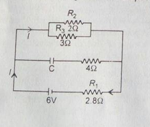
View SolutionCalculate the steady state current in the 2Ω resistor, shown in figure. The internal resistance of the battery is negligible and the capacitance of the capacitor C is 0.2μF.

View Solution
