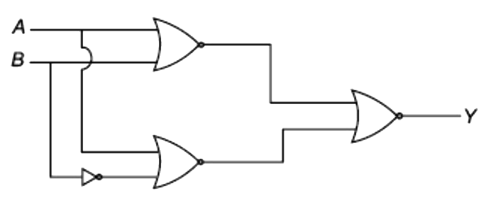
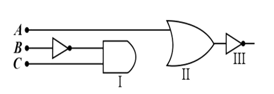
The output (X) of the logic circuit shown in figure will be

A
X=¯¯¯¯¯¯¯A.¯¯¯¯¯¯B
B
X=¯¯¯¯¯¯¯¯A.B
C
X=A.B
D
A=¯¯¯¯¯¯¯¯¯¯¯A+B
Video Solution
Text Solution
The correct Answer is:C
|
Answer
Step by step video, text & image solution for The output (X) of the logic circuit shown in figure will be by Physics experts to help you in doubts & scoring excellent marks in Class 12 exams.
Updated on:21/07/2023Topper's Solved these Questions
Similar Questions
Knowledge Check
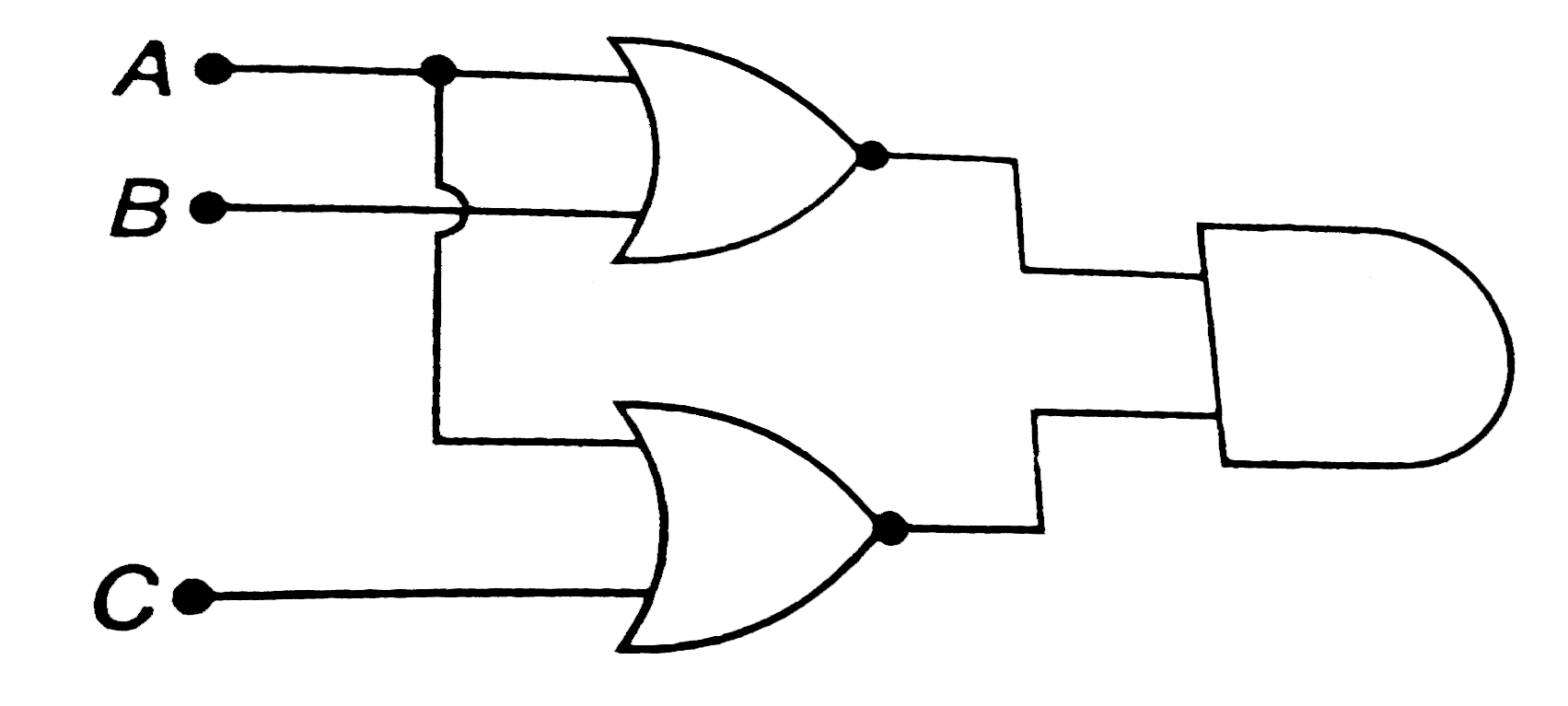
The output Y of the logic circuit as shown in figure is
 A(A+B)⋅¯¯¯CB(A+C)⋅¯¯¯CC(B+C)⋅¯¯¯ADA+B+C
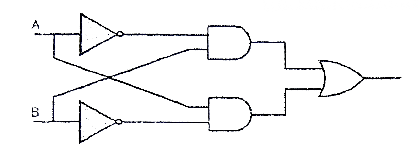
The output Y of the logic circuit as shown in figure is best represents as
 A¯¯¯A+¯¯¯¯¯¯¯¯¯B⋅CBA+¯¯¯B⋅CC¯¯¯¯¯¯¯¯¯¯¯¯¯¯¯¯¯A+B⋅CD¯¯¯¯¯¯¯¯¯¯¯¯¯¯¯¯¯A+¯¯¯B⋅C
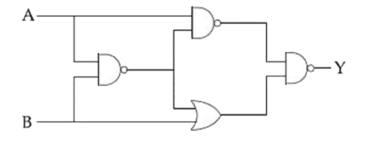
The outpout Y of the logic circuit shown in figure is best represented as
 A¯¯¯A+¯¯¯B.¯¯¯CB¯¯¯A+¯¯¯B.CC¯¯¯A+B.¯¯¯CD(¯¯¯A+¯¯¯B)C

