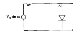
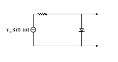
The output Y of the gate circuit shown in the figure below is

A
B
C
D
Video Solution
Text Solution
The correct Answer is:B
The input of AND gate is
|
Topper's Solved these Questions
- SEMICONDUCTOR ELECTRONICSBook:NARAYNAChapter:SEMICONDUCTOR ELECTRONICSExercise:EXERCISE -2 (H.W) (INTRINSIC, EXTRINSIC SEMICONDUCTORS)
Explore 6 Videos
- SEMICONDUCTOR ELECTRONICSBook:NARAYNAChapter:SEMICONDUCTOR ELECTRONICSExercise:EXERCISE -2 (H.W) (JUNCTION DIODES)
Explore 5 Videos
- SEMICONDUCTOR ELECTRONICSBook:NARAYNAChapter:SEMICONDUCTOR ELECTRONICSExercise:EXERCISE -2 (C.W) (TRANSISTORS)
Explore 11 Videos
- SEMI CONDUCTOR DEVICESBook:NARAYNAChapter:SEMI CONDUCTOR DEVICESExercise:Level-II (H.W)
Explore 36 Videos
- WAVE OPTICSBook:NARAYNAChapter:WAVE OPTICSExercise:Exercise - 4 Polarisation
Explore 9 Videos
Similar Questions
Knowledge Check
The output Y of the logic circuit as shown in figure is
 A(A+B)⋅¯¯¯CB(A+C)⋅¯¯¯CC(B+C)⋅¯¯¯ADA+B+C
The circuit shown in figure below will act as
 AOR gateBAND gateCXOR gateDNone of these
The output (X) of the logic circuit shown in figure will be
 AX=¯¯¯¯¯¯¯A.¯¯¯¯¯¯BBX=¯¯¯¯¯¯¯¯A.BCX=A.BDX=¯¯¯¯¯¯¯¯¯¯¯A+B
The output (X) of the logic circuit shown in figure will be

View SolutionThe output (X) of the logic circuit shown in figure will be

View SolutionThe output Y of the logic circuit as shown in figure is best represents as

View SolutionThe output of the given circuit in Figure

View SolutionThe output of the given circuit in figure:

View Solution


