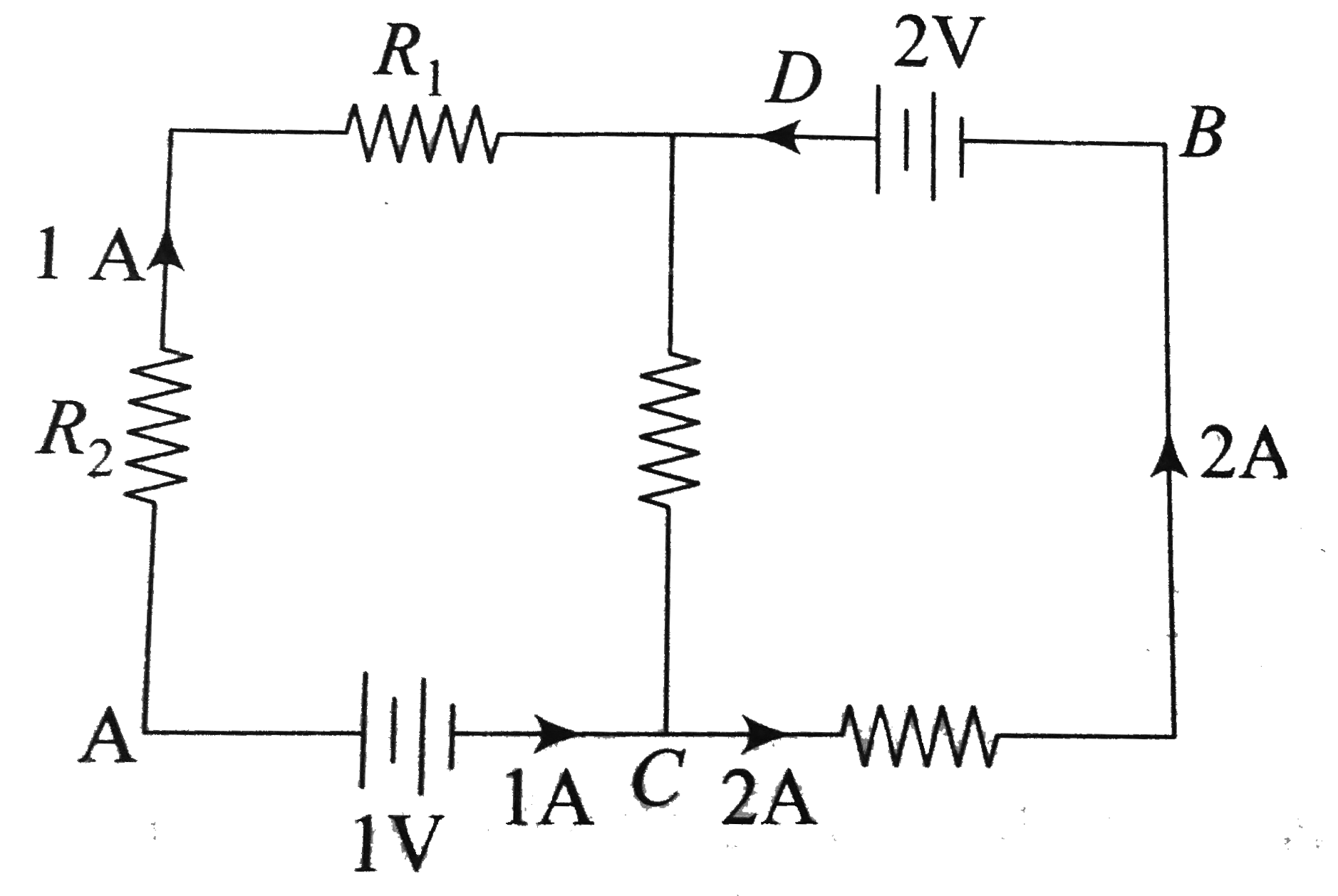
In the circuit shown in the , the potential of point A with respect to point B is

2 V
−2V
−1.5V
+1.5V
The correct Answer is:C
Hint : For the whole loop , 2.5−1=10I+20I=30I
∴I=1.530=120A,VBA=2.5−120×10−0.5=1.5V
∴VAB=−1.5V
Topper's Solved these Questions
- KIRCHHOFF'S LAWS AND ELECTRICAL MEASUREMENT BOOK - CHHAYA PUBLICATIONCHAPTER - KIRCHHOFF'S LAWS AND ELECTRICAL MEASUREMENT EXERCISE - EXERCISE (Very Short Answer Type Questions )
12 Videos
- KIRCHHOFF'S LAWS AND ELECTRICAL MEASUREMENT BOOK - CHHAYA PUBLICATIONCHAPTER - KIRCHHOFF'S LAWS AND ELECTRICAL MEASUREMENT EXERCISE - EXERCISE ( Short Answer Type Questions - I )
7 Videos
- KIRCHHOFF'S LAWS AND ELECTRICAL MEASUREMENT BOOK - CHHAYA PUBLICATIONCHAPTER - KIRCHHOFF'S LAWS AND ELECTRICAL MEASUREMENT EXERCISE - NCERT EXEMPLAR QUESTIONS WITH ANSWER HINT (MCQ -2)
1 Video
- ELEMENTARY PHENOMENA OF ELECTROSTATICS BOOK - CHHAYA PUBLICATIONCHAPTER - ELEMENTARY PHENOMENA OF ELECTROSTATICS EXERCISE - EXAMINATION ARCHIVE
2 Videos
- LIGHT WAVE AND INTERFERENCE OF LIGHT BOOK - CHHAYA PUBLICATIONCHAPTER - LIGHT WAVE AND INTERFERENCE OF LIGHT EXERCISE - CBSE SCANNER
15 Videos
Similar Questions
In the circuit , gives in the figure currents in different branches and value of one resistor are shown . Then potential at point B with respect to the point A is :
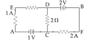
View SolutionIn the circuit , gives in the figure currents in different branches and value of one resistor are shown . Then potential at point B with respect to the point A is :

View Solution
Knowledge Check
In a circuit shown in the figure, what is potential of point A?
 A2VB5VC8VD4V
In the circuit shown if point O is earthed, the potential of point X is equal to
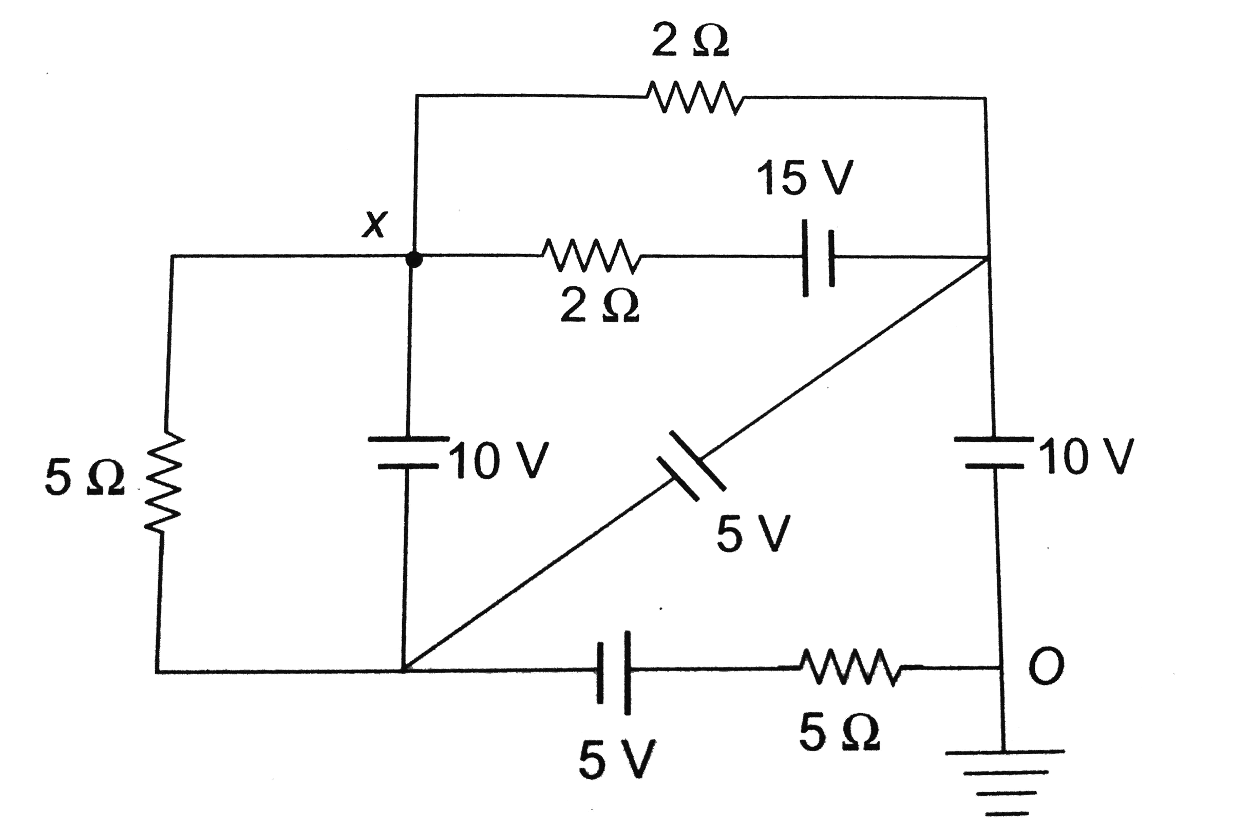 A10VB15VC25VD12.5V
In the circuit shown in the figure, if the potential at point A behind to be zero, the potential at point B is :
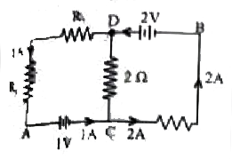 A−1VB+2VC−2VD+1V
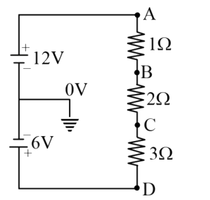
In the circuit diagram shown in Figure , the potentials of the points B, C and D are respectively -
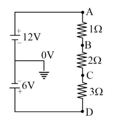
View SolutionIn the circuit diagram shown in Figure , the potentials of the points B, C and D are respectively -

View SolutionIn the circuit shown in the figure, if potentail at point A is taken to be zero, the potential at point B is
View SolutionIn the circuit diagram shown in figure, the potentials of the points B, C and D are respectively.
View SolutionIn the circuit shown in the figure, if potentail at point A is taken to be zero, the potential at point B is

View Solution
