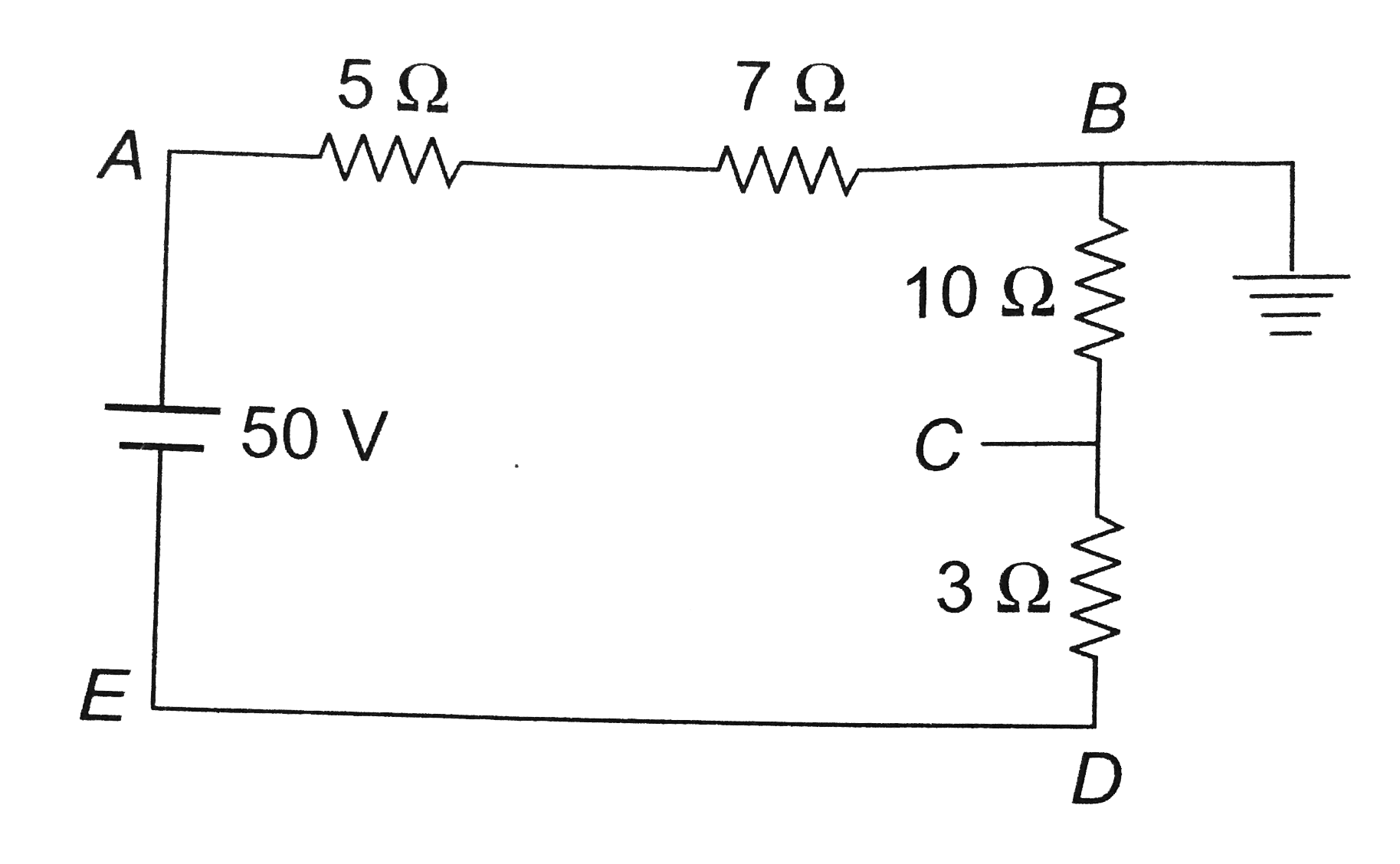
In the circuit diagram shown in Figure , the potentials of the points B, C and D are respectively -
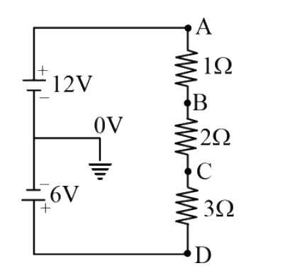
12V, 10V, 6V
11V, 9V, 6V
11V, 9V, 0V
12V, 10V, 0V
The correct Answer is:B
Step by step video & image solution for In the circuit diagram shown in Figure , the potentials of the points B, C and D are respectively - by Physics experts to help you in doubts & scoring excellent marks in Class 12 exams.
Updated on:21/07/2023Similar Questions
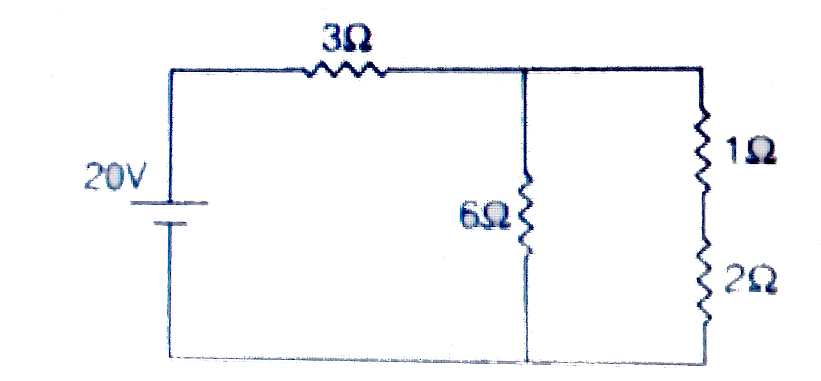
In the circuit shown in figure potential difference across
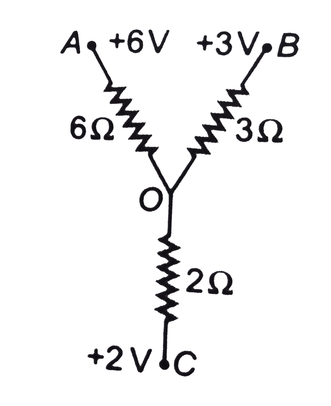
View SolutionThree resistance are joined together to form a letter Y, as shown in figure. If the potentials of the terminals A,B and C are 6V,3V and 2V respectively, then the potential of the point O will be
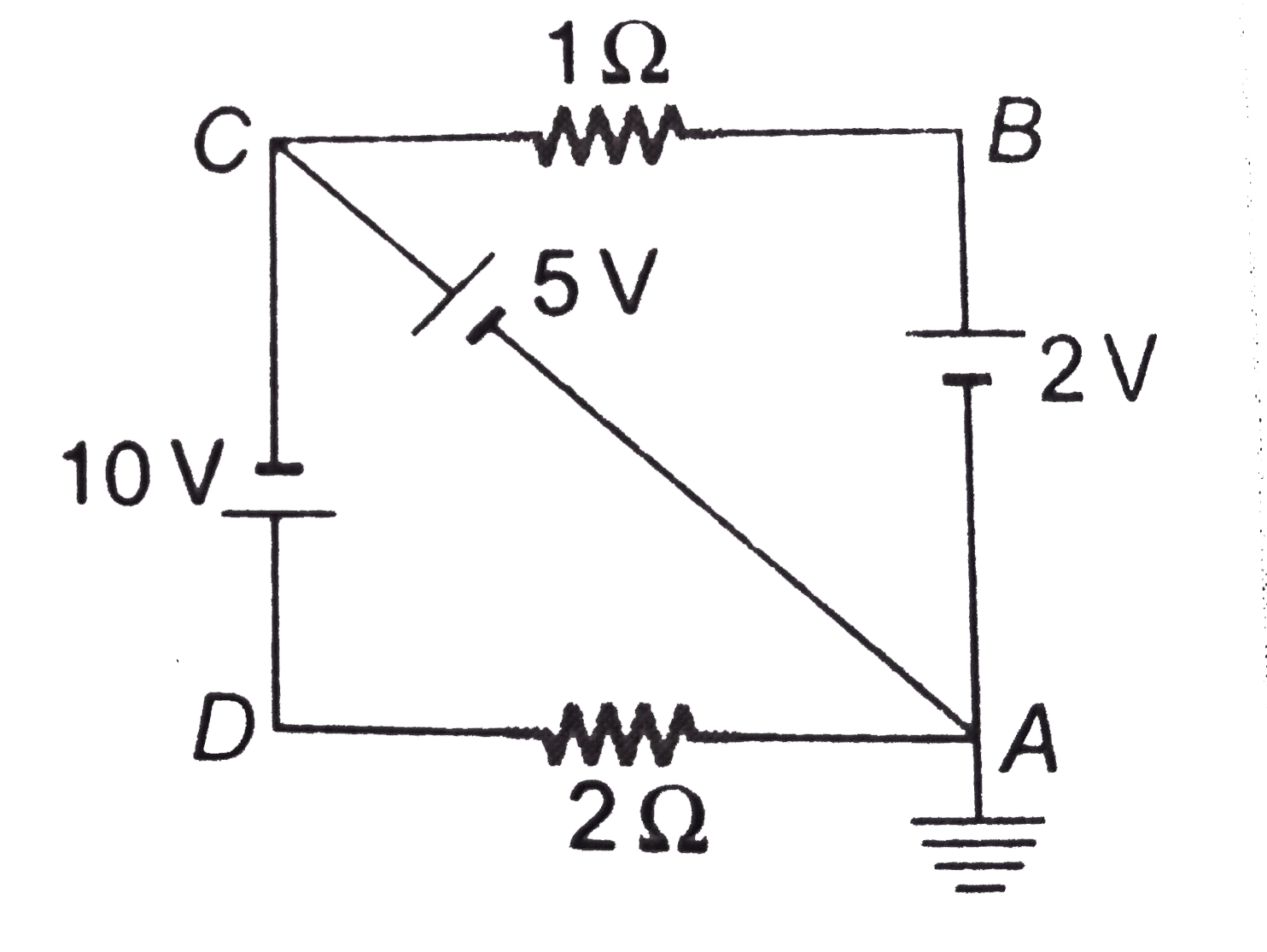
View SolutionIn the circuit shown in figure find the potentials of A,B,C and D and the current through 1Ω and 2Ω resistance.
View SolutionIn the circuit shown, the point B is earthed. The potential at the point 'A' is
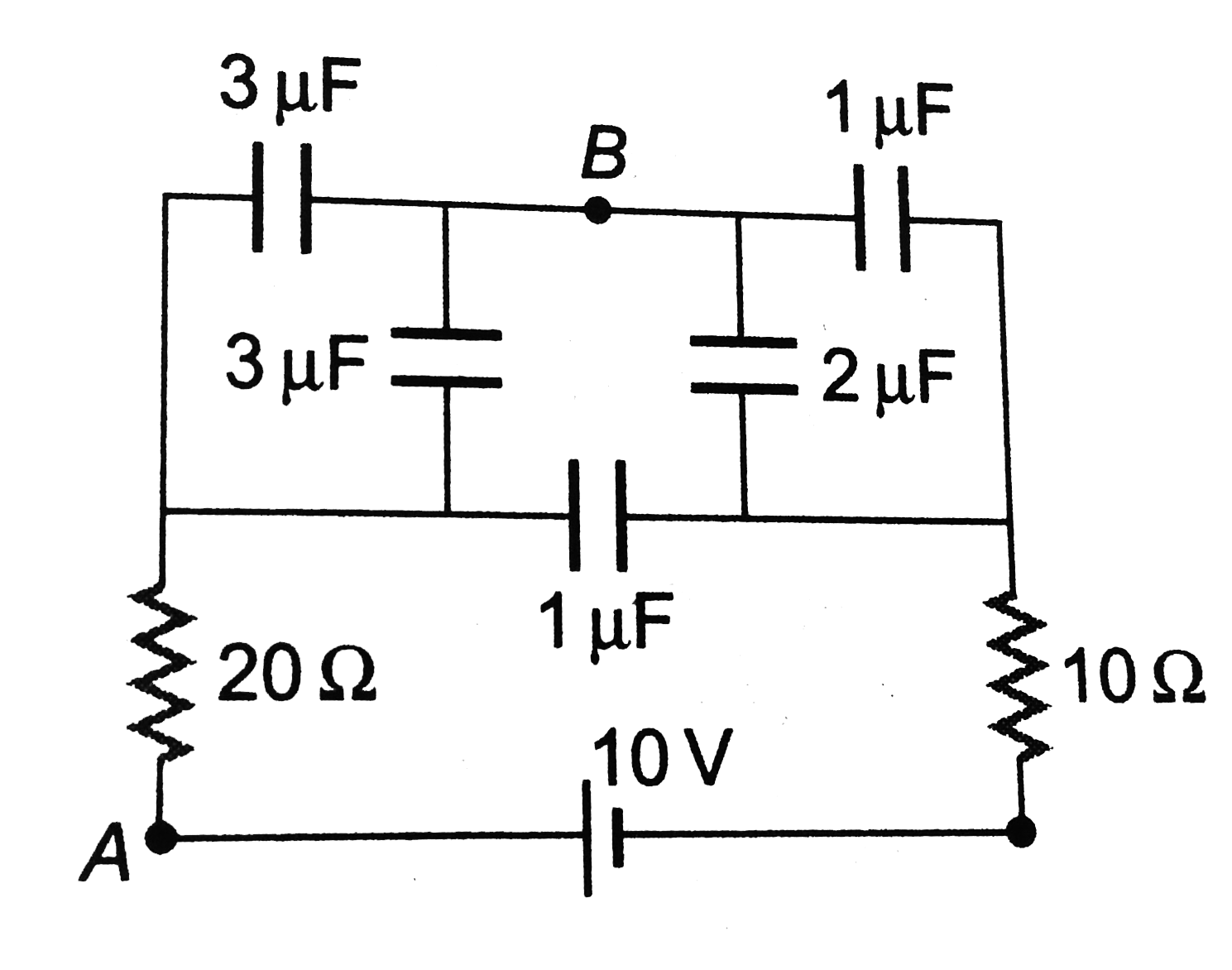
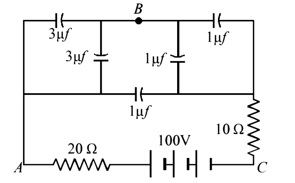
View SolutionIn the circuit shown in figure potential difference between the points A and B in the steady state is
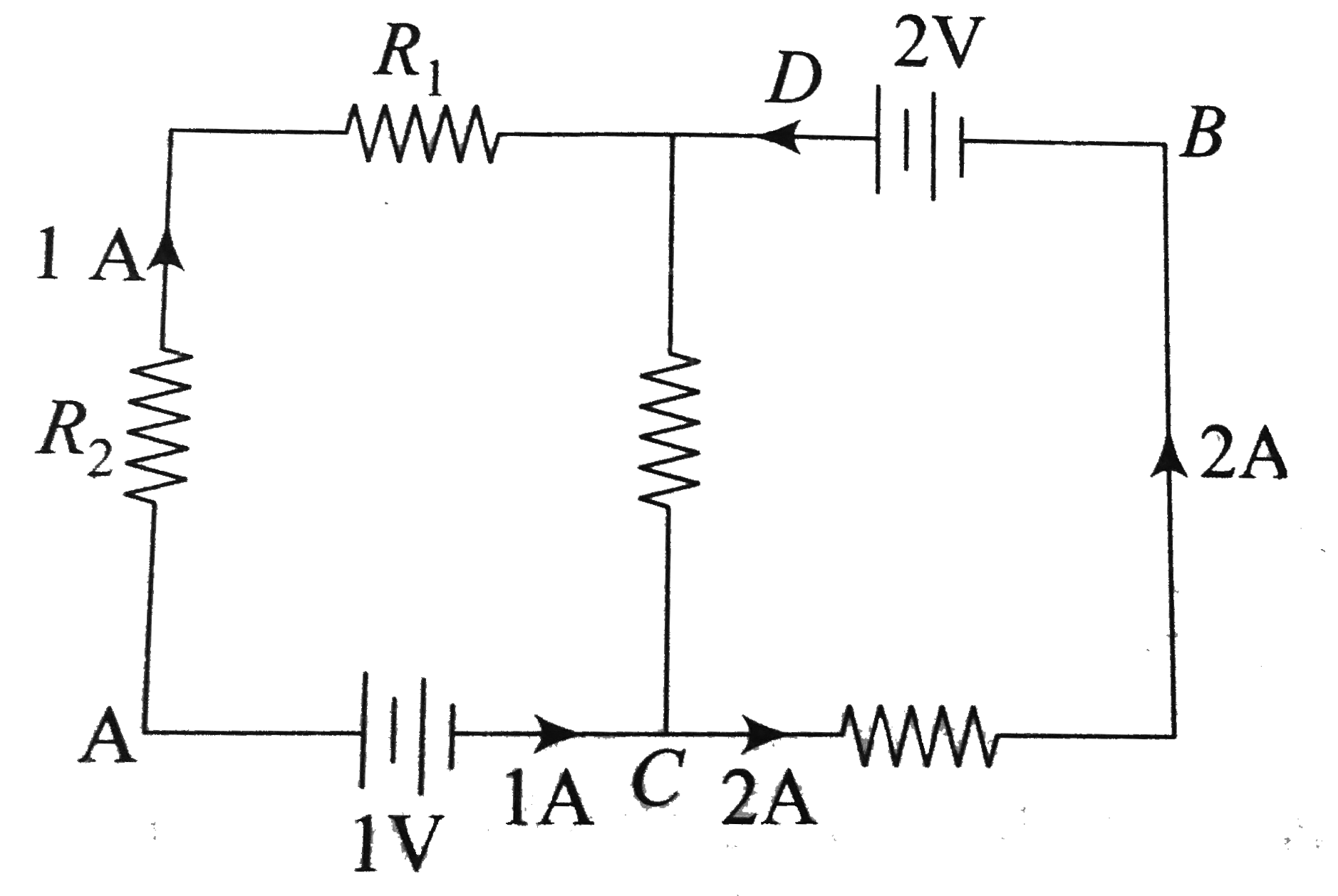
View SolutionIn the circuit shown in the figure, if potentail at point A is taken to be zero, the potential at point B is
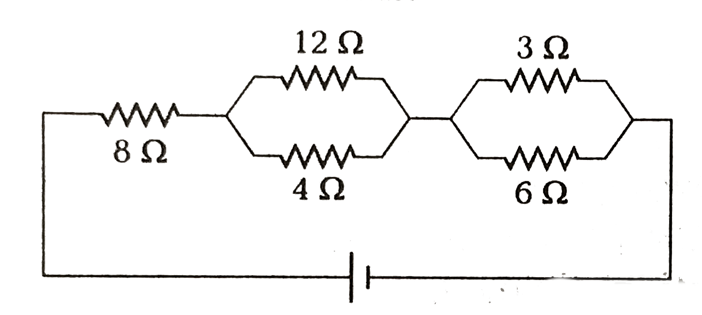
View SolutionIn the circuit diagram shown in figure, potential difference across 3Ω resistance is 20 V. Then, match the following two columns.
View SolutionIn the diagram shown find the potential difference between the points A and B and between the points B and C in the steady state.
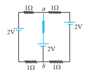
View SolutionFor the circuit figure, find the potential difference between points a and b:
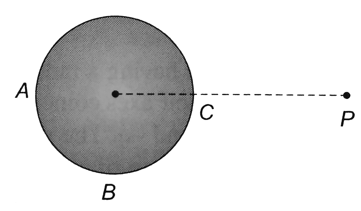
View SolutionA hollow conducting sphere is placed in an electric field produced by a point charge placed at P as shown in figure.
Let VA,VB,VC be the potentials at points A,BandC respectively. Then
View Solution
