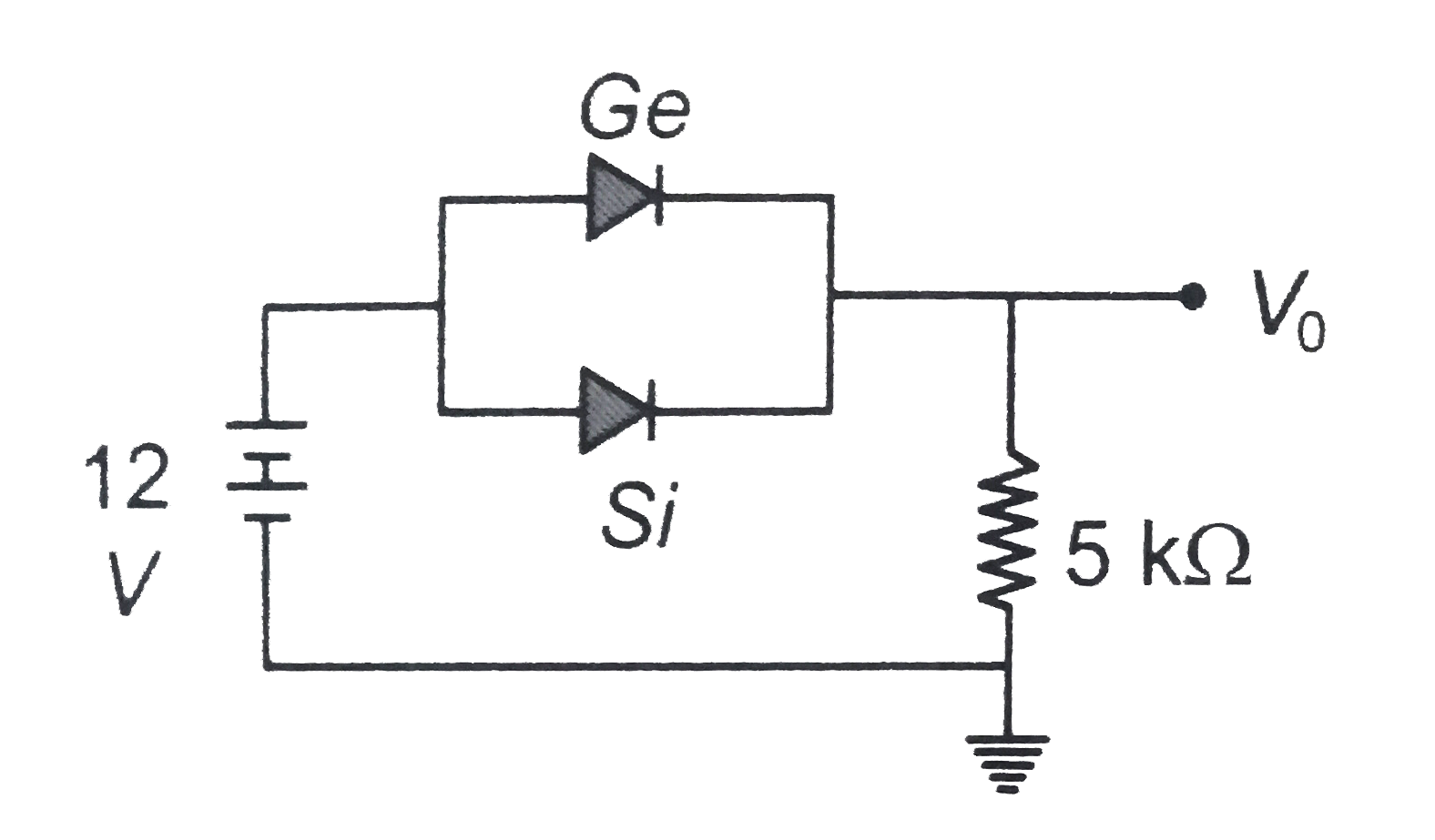
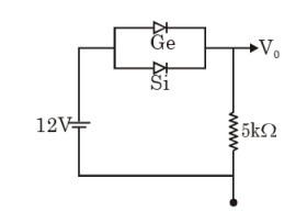
and diodes conduct at and respectively. In the following figure if diode connection are reversed, the value of changes by
The correct Answer is:B
Step by step video, text & image solution for Ge and Si diodes conduct at 0.3 V and 0.7 V respectively. In the following figure if Ge diode connection are reversed, the value of V_(0) changes by by Physics experts to help you in doubts & scoring excellent marks in Class 12 exams.
Updated on:21/07/2023Topper's Solved these Questions
- ELECTRONICSBOOK - ERRORLESS CHAPTER - ELECTRONICSEXERCISE - Digital Electronics
2 Videos
- ELECTRONICSBOOK - ERRORLESS CHAPTER - ELECTRONICSEXERCISE - Valve Electronics (Diode and Triode)
3 Videos
- ELECTRON, PHOTON, PHOTOELECTRIC EFFECT AND X-RAYSBOOK - ERRORLESS CHAPTER - ELECTRON, PHOTON, PHOTOELECTRIC EFFECT AND X-RAYSEXERCISE - Self Evaluation Test
3 Videos
- ELECTROSTATICS BOOK - ERRORLESS CHAPTER - ELECTROSTATICS EXERCISE - Ordinary Thinking Objective Questions (Electric Flux and Gauss.s Law)
28 Videos
Similar Questions
Calculate the value of output voltageV0 and I if the Si diode and the Ge diode conduct at 0.7 V and 0.3V respectively, in the circuit given in Fig. If now Ge diode connections are reversed, what will be the new values of V0 and I.
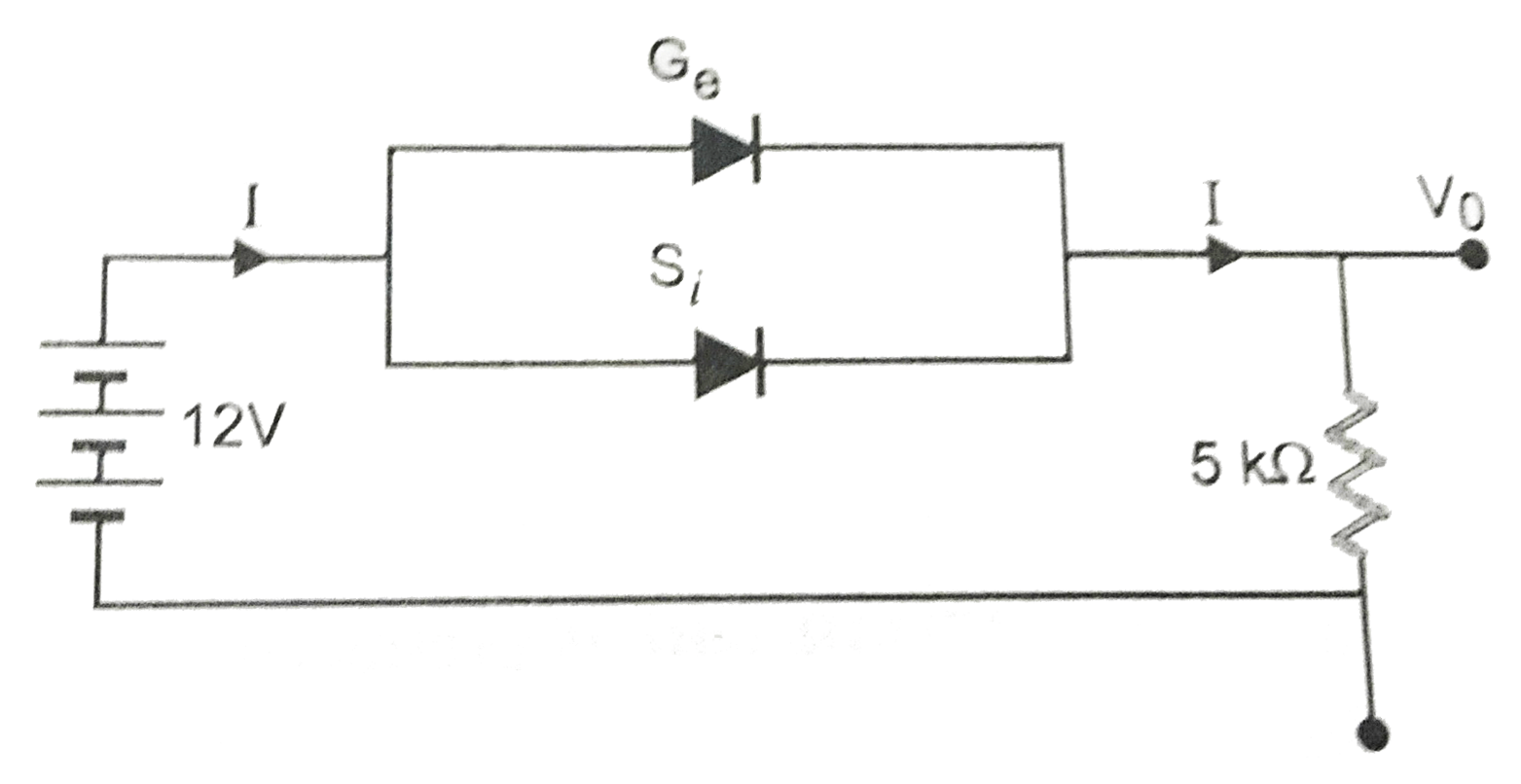
View SolutionCalculate the value of output voltageV0 and I if the Si diode and the Ge diode conduct at 0.7 V and 0.3V respectively, in the circuit given in Fig. If now Ge diode connections are reversed, what will be the new values of V0 and I.

View Solution
Knowledge Check
In the circuit shown in figure, the silicon and germanium diodes start conducting at 0.7 V and 0.3 V respectively. What are the values of V0 and I?
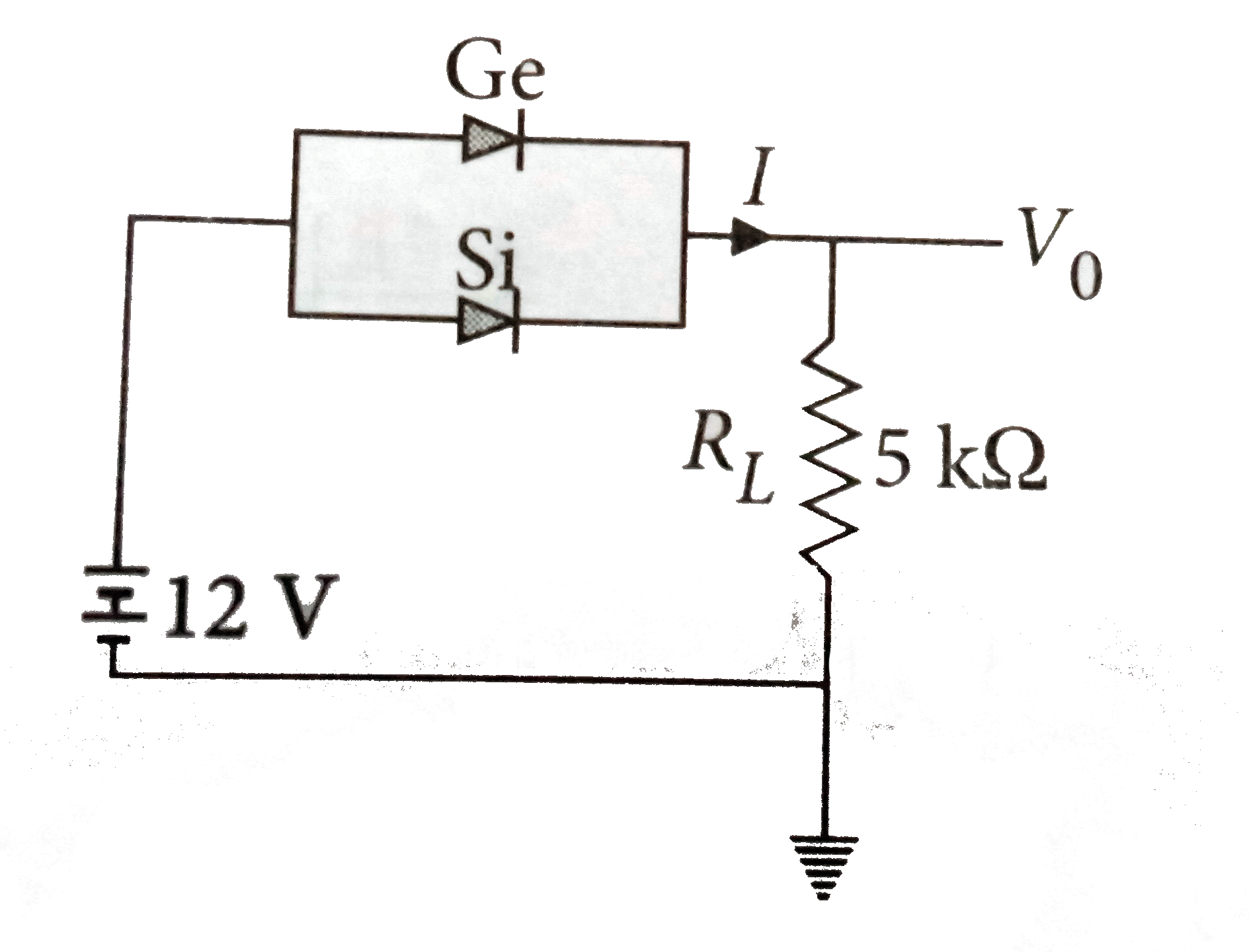 A12 V, 2.4 mAB11.7 V, 2.34 mAC11.3 V, 2.26 mAD11 V, 2.2 mA
In the circuit shown in figure, if the diode forward voltage drop is 0.3 V, then the voltage difference between A to B is,
 A1.3 VB2.3 VCzeroD0.5V
In the circuit shown in figure, if the A diode forward voltage drop is 0.3 V, the voltage difference between A and B is
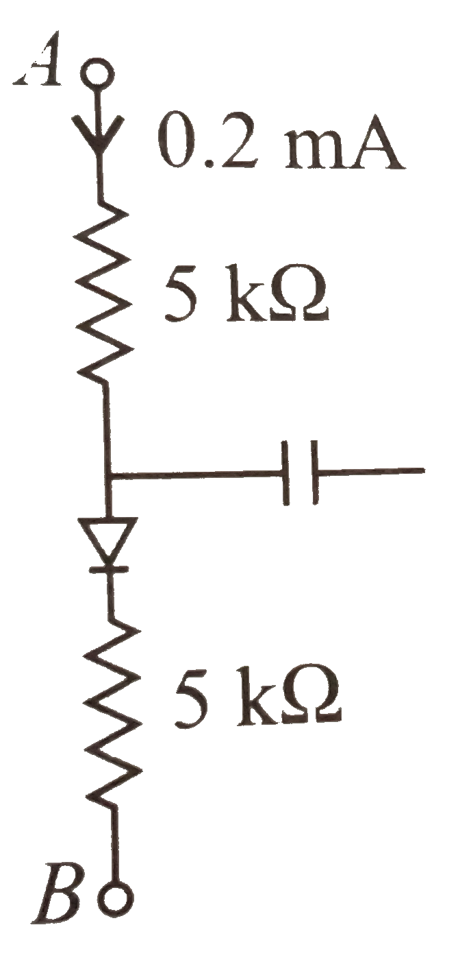 A1.3 VB2.3 VC0D0.5 V
Calculate the value of output voltage V0 (in V) if the Si diode and Ge diode conduct at 0.7V and 0.3V respectively. Fig.
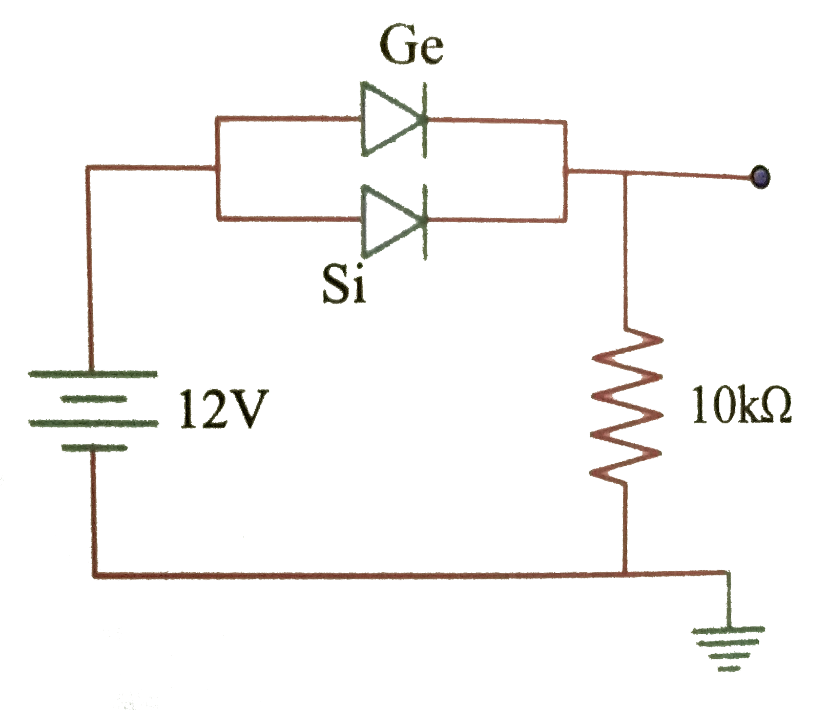
View SolutionTwo junction diodes, one of germanium (Ge) and other of silicon (Si) are connected as shown in fig to a battery of 12V and a load resistance 10kΩ. The germanium diode conducts at 0.3V and silicon diode at 0.7V. When current flows in the circuit, the potential of terminal Y will be
 .
.
View SolutionA junction diode is connected to a 10V source and 103Ω rheostat. The slope of load line on the characteristic curve of diode by (inA/V).
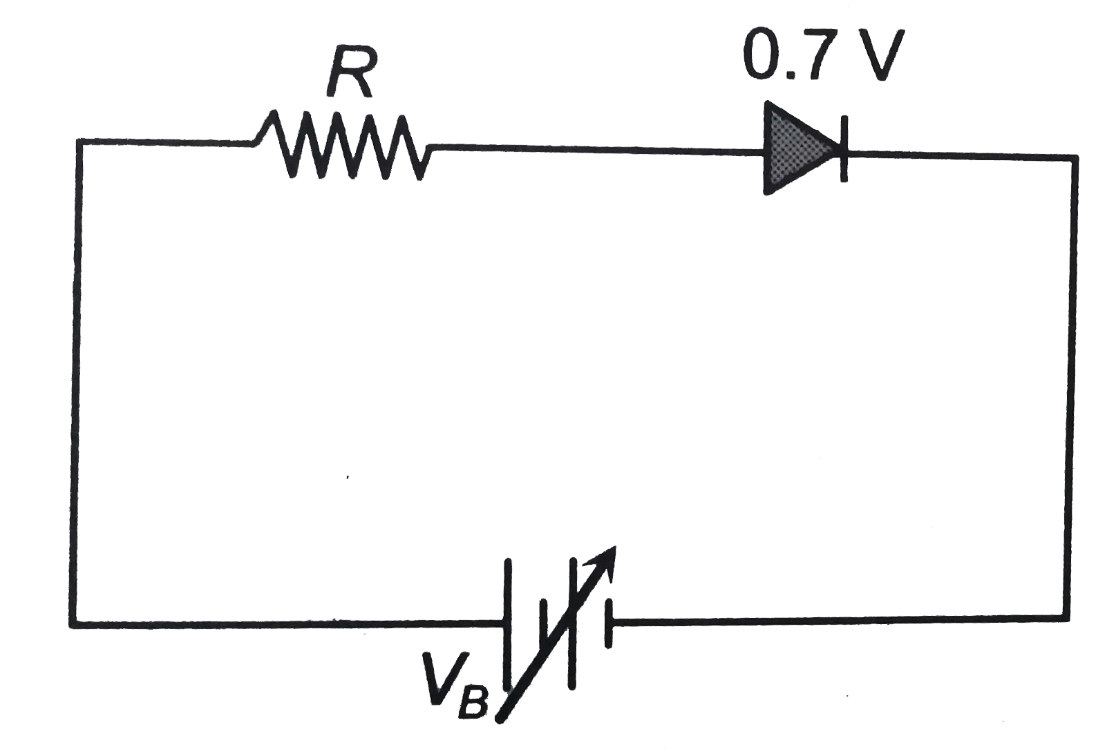
View SolutionThe junction diode in the following circuit requires a minimum current of 1mA to be above the knee point (0.7V) of its I−V characterstic curve. The voltage across the diode is independent of current above the knee point. If VB=5V, then the maximum value of R so that the voltage is above the knee point, will be
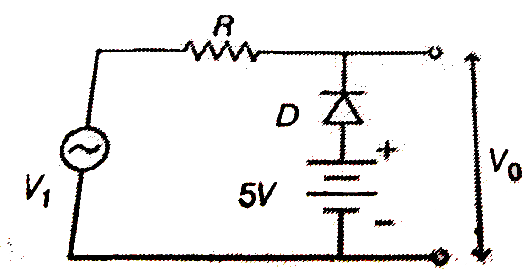
View SolutionIn the figure, D is an ideal diode and an alternating voltage of peak value 10 volts si connected as input V1. Which of the following figures represents the correct waveform of output voltage V0 ?
View Solution
