Consider a simple circuit shown in Fig. 2(ET).2. stands for a variable resistance R'.R' can vary from to infinity. r is internal resistance of the battery
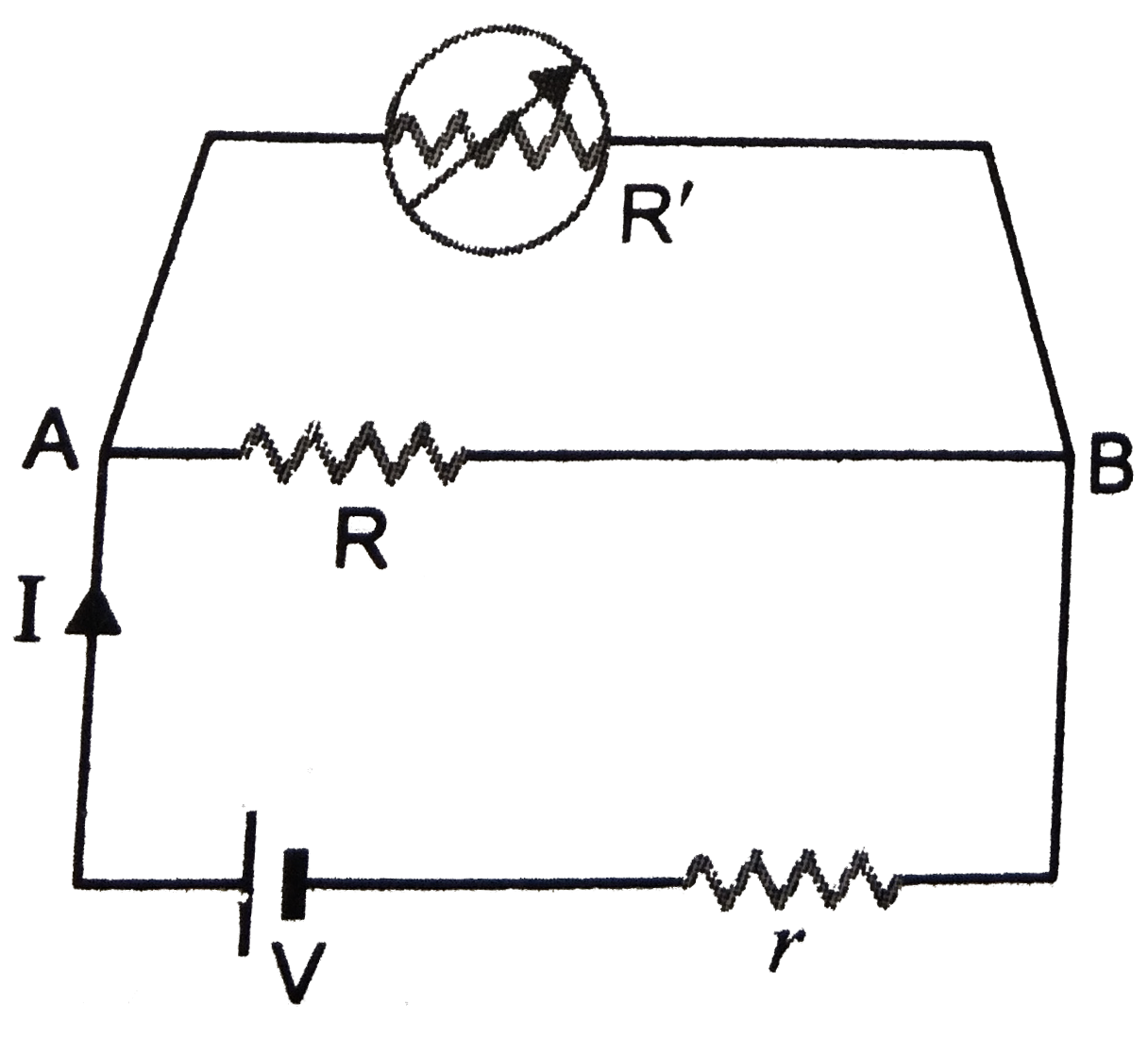
Potential drop across AB is nealry constant as is varied
Current through is nearly a constant as is varied
Current I depends sensitivity on
always
The correct Answer is:A, D
Step by step video, text & image solution for Consider a simple circuit shown in Fig. 2(ET).2. stands for a variable resistance R'.R' can vary from R_(0) to infinity. r is internal resistance of the battery (rltltRltltlR_(0)) by Physics experts to help you in doubts & scoring excellent marks in Class 12 exams.
Updated on:21/07/2023Topper's Solved these Questions
- ELECTRIC CURRENT & CIRCUITSBOOK - CENGAGE PHYSICSCHAPTER - ELECTRIC CURRENT & CIRCUITSEXERCISE - Kirchhoff s Law and Grouping Cells
15 Videos
- ELECTRIC CHARGES AND FIELDSBOOK - CENGAGE PHYSICSCHAPTER - ELECTRIC CHARGES AND FIELDSEXERCISE - QUESTION BANK
40 Videos
- ELECTRIC CURRENT AND CIRCUITBOOK - CENGAGE PHYSICSCHAPTER - ELECTRIC CURRENT AND CIRCUITEXERCISE - Interger
8 Videos
Similar Questions
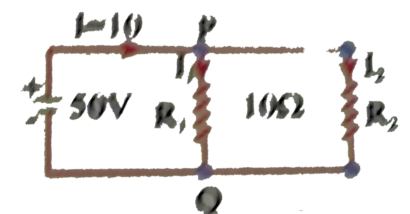
For a circuit shown in fig find the value of resistance R2 and current I2 flowing thorugh R2
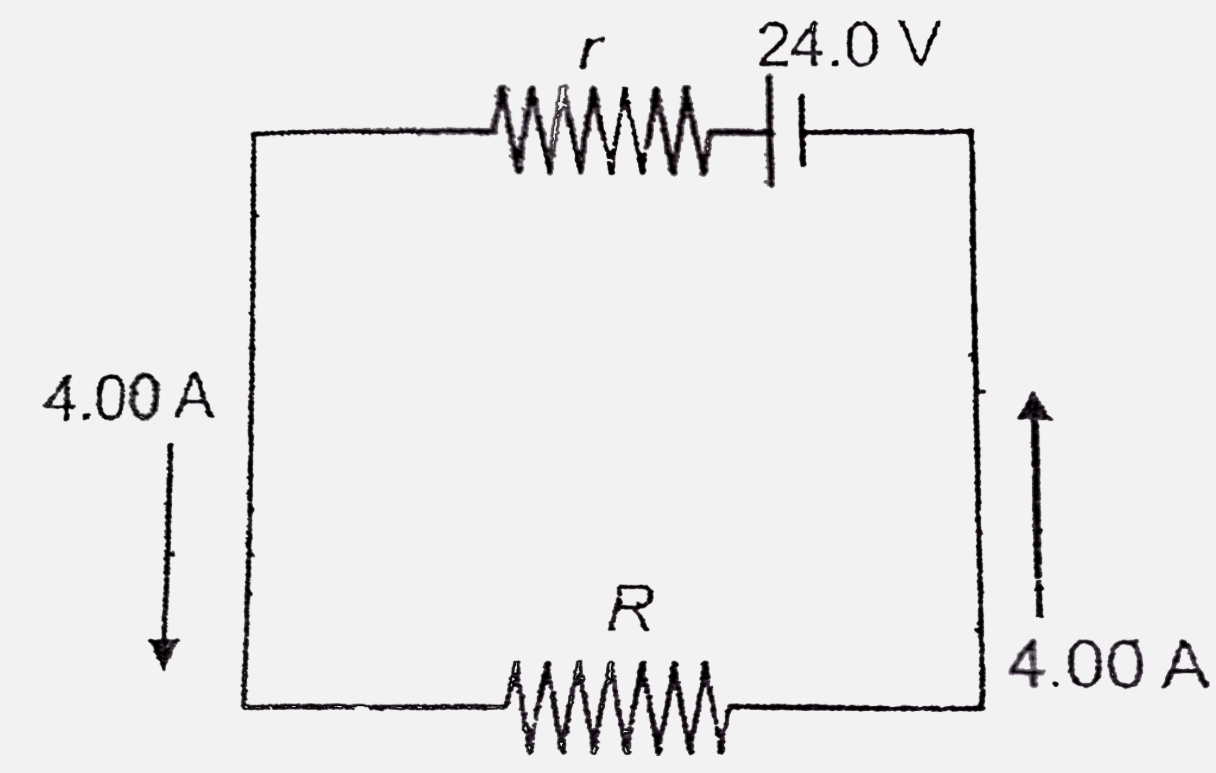
View SolutionConsider the circuit shown in Figure . The terminal voltage of the 24.0 V battery is 21.2V. What are
(a) The internal resistance r of the battery and
(b) The resistance R of the circuit resistor ?
View Solution
Knowledge Check
For maximum power from battery the internal resistance of battery r is
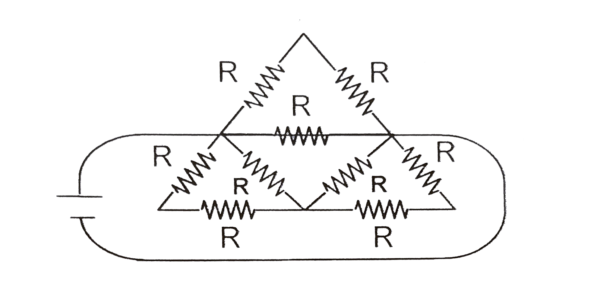 A10RB4R9CR8D10R9
Consider the circuit shown in fig.
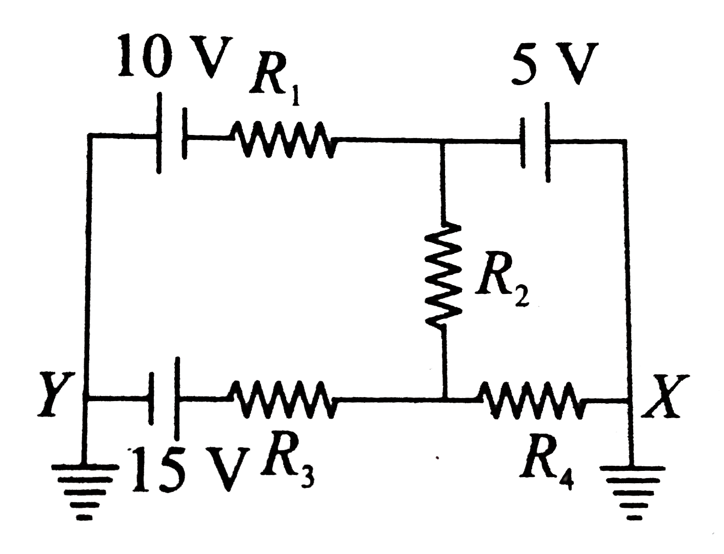
Assuming R1=2Ω, current passing through resistance R1 isA2AB2.5AC3.5ADzeroIn the circuit shows in Fig. 6.42, resistors X and Y, each with resistance R, are connected to a 6V battery of negligible internal resistance. A voltmetre, also of resistance R, is connected across Y.
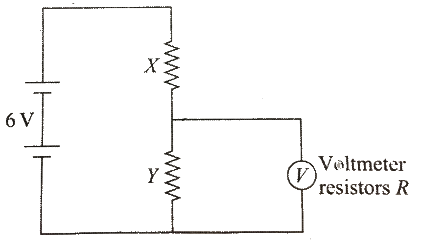
What is the reading of the voltmeter?AzeroBbetween0and3 VC3VDbetween3 Vand6 V
Find the current flowing current flowing thorugh the resistance R in the circuit shown in Fig. The internal resistances of the batteries are negilble.

View SolutionA battery of emf ε and internal resistance r sends currents I1 and I2, when connected to external resistance R1 and R2 respectively. Find the emf and internal resistance of the battery.
View SolutionIn the circuit shown in Fig. the emf of the sources is equal to ξ=5.0V and the resistances are equal to R1=4.0Ω and R2=6.0Ω. The internal resistance of the source equals R=1.10Ω. Find the currents flowing through the resistances R1 and R2.

View SolutionConsider circuit as shown . Which of the graph best represent V-l relationship across the variable resistance R.
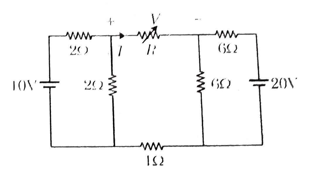
View SolutionIn the circuit shown in the given figure, the resistances R1andR2 are respectively

View Solution
