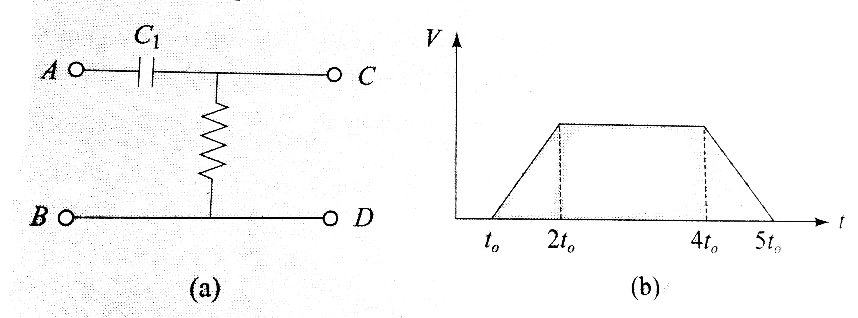
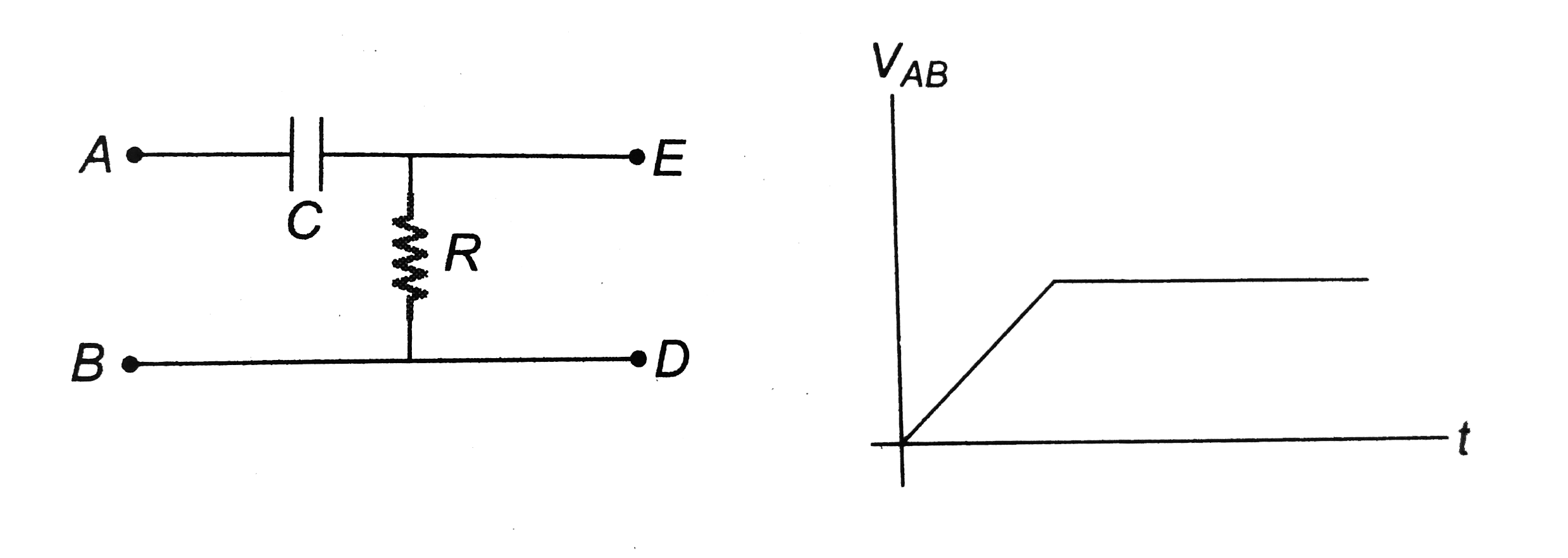
A time varying voltage is applied to the clamps A and B such that voltage across the capacitor plates is as shown in the figure. Plot the time dependence of voltage across the terminals of the esistance E and D.
Video Solution
|
Answer
Step by step video & image solution for A time varying voltage is applied to the clamps A and B such that voltage across the capacitor plates is as shown in the figure. Plot the time dependence of voltage across the terminals of the esistance E and D. by Physics experts to help you in doubts & scoring excellent marks in Class 12 exams.
Updated on:21/07/2023
Topper's Solved these Questions
Similar Questions
Knowledge Check
- Question 1 - Select One
If A.C. voltage is applied to a pure capacitor, then votage across the capacitor ………….. .
Aleads the current by phase angle (π2) rad.Bleads the current by phase angle (π) rad.Clags behind the current by phase angle (π2)rad.Dlags behind the current by phase angle (π) rad. - Question 2 - Select One
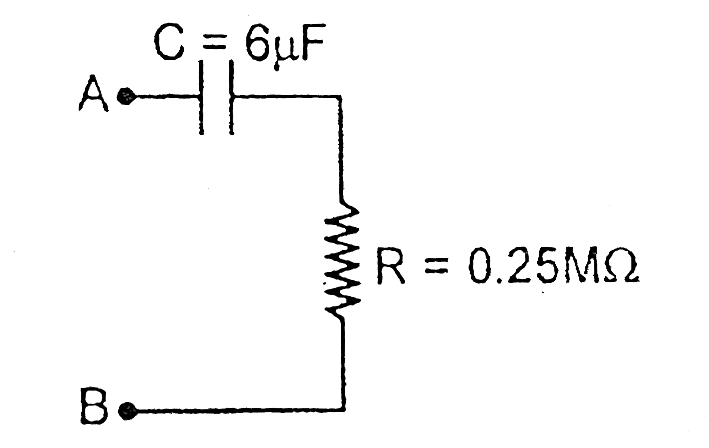
A time varying voltage is applied across A & B such that voltage across capacitor is given by VC=2sin2t. What is maximum potential difference across the reistance?
 A9VB18VC3VD6V
 - Question 3 - Select One
Let q be the charge on the capacitor at any time t. The voltage V across the capacitor is
AVmsinωt=qCBVmcosωt=2VCCVmcosωt=q2CDVmsinωt=2qC
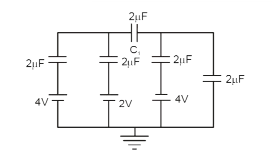
 Find voltage across capacitor C1. View Solution
In given LCR circuit, the voltage across the terminals of a resistance & current will be–
 View Solution
If a voltage V is applied across the bulbs in series then
View Solution120 V AC voltage is applied to 10 ohm resistance. The peak voltage across the resistor is
View SolutionIn the circuit shown in figure, the final voltage drop across the capacitor C is :
 View Solution


