The figure shows three non condncting rods, one circular and two straight. Each has a uniform charge of magnitude Q distributed on its one half and -Q on its other half as shown in the figure-1.364. Which of these correctly represents the direction of field at point P :
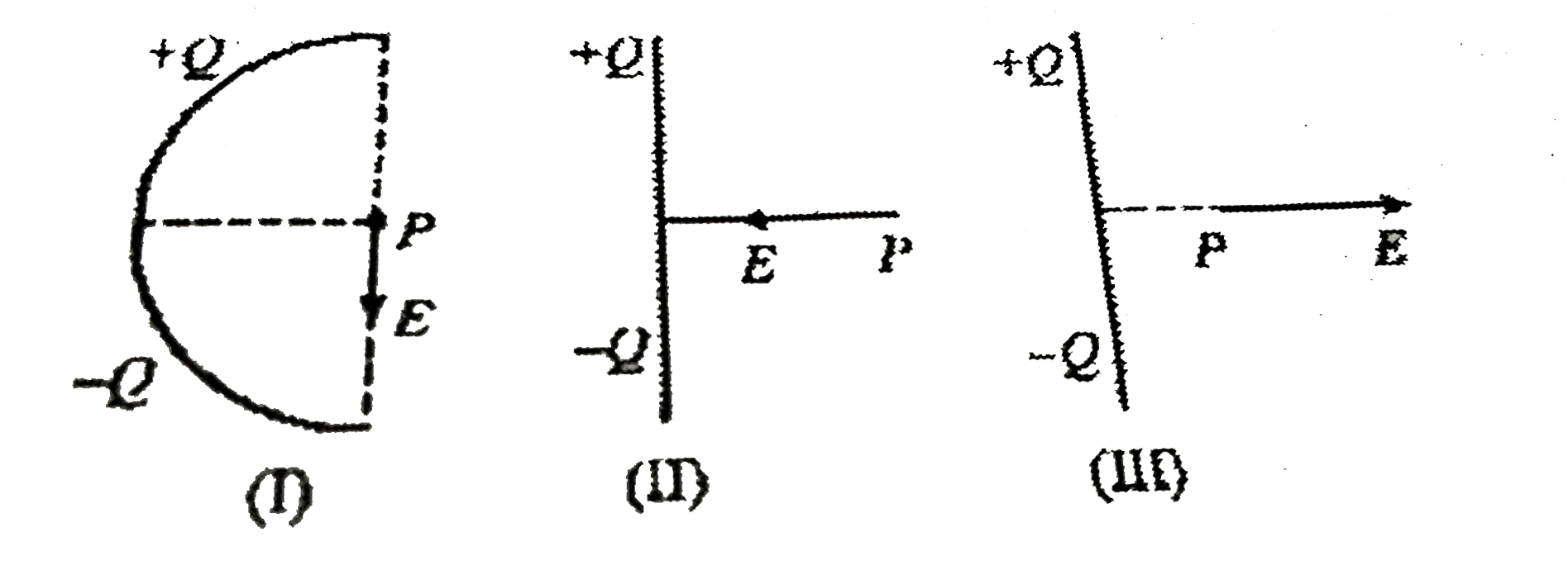
I
II
III
I and II
Step by step video & image solution for The figure shows three non condncting rods, one circular and two straight. Each has a uniform charge of magnitude Q distributed on its one half and -Q on its other half as shown in the figure-1.364. Which of these correctly represents the direction of field at point P : by Physics experts to help you in doubts & scoring excellent marks in Class 12 exams.
Updated on:21/07/2023Topper's Solved these Questions
- ELECTROSTATICSBOOK - PHYSICS GALAXY - ASHISH ARORACHAPTER - ELECTROSTATICSEXERCISE - Numerical MCQs Single options Correct
64 Videos
- ELECTROSTATICSBOOK - PHYSICS GALAXY - ASHISH ARORACHAPTER - ELECTROSTATICSEXERCISE - Advance MCQs
40 Videos
- ELECTROSTATICSBOOK - PHYSICS GALAXY - ASHISH ARORACHAPTER - ELECTROSTATICSEXERCISE - Discussion Question
25 Videos
- ELECTROMAGNETIC INDUCTION AND ALTERNATING CURRENTBOOK - PHYSICS GALAXY - ASHISH ARORACHAPTER - ELECTROMAGNETIC INDUCTION AND ALTERNATING CURRENTEXERCISE - Advance MCQs
33 Videos
- GEOMETRICAL OPTICSBOOK - PHYSICS GALAXY - ASHISH ARORACHAPTER - GEOMETRICAL OPTICSEXERCISE - Unsolved Numerical Problems
107 Videos
Similar Questions
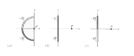
The figure here shows three nonconducting rods, one circular and two straight. Each has a uniform charge of magnitude Q along its top half and another along its bottom half. For each rod, what is the direction of the net electric field at point P ?
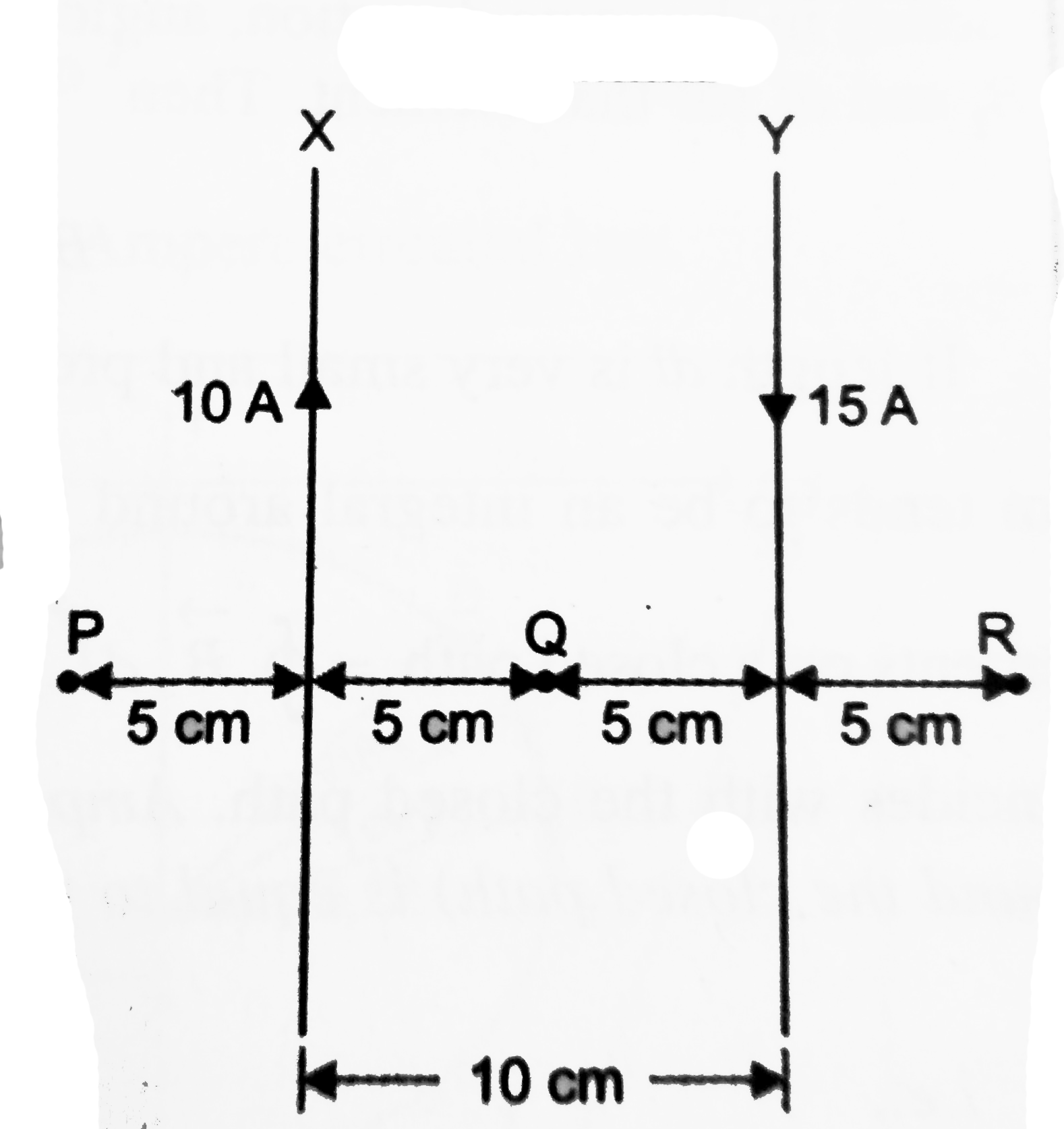
View SolutionThere are two parallel current carrying wires X and Y as shown in figure. Find the magnitude and direction of the magnetic field at points, P, Q and R.
View Solution
Knowledge Check
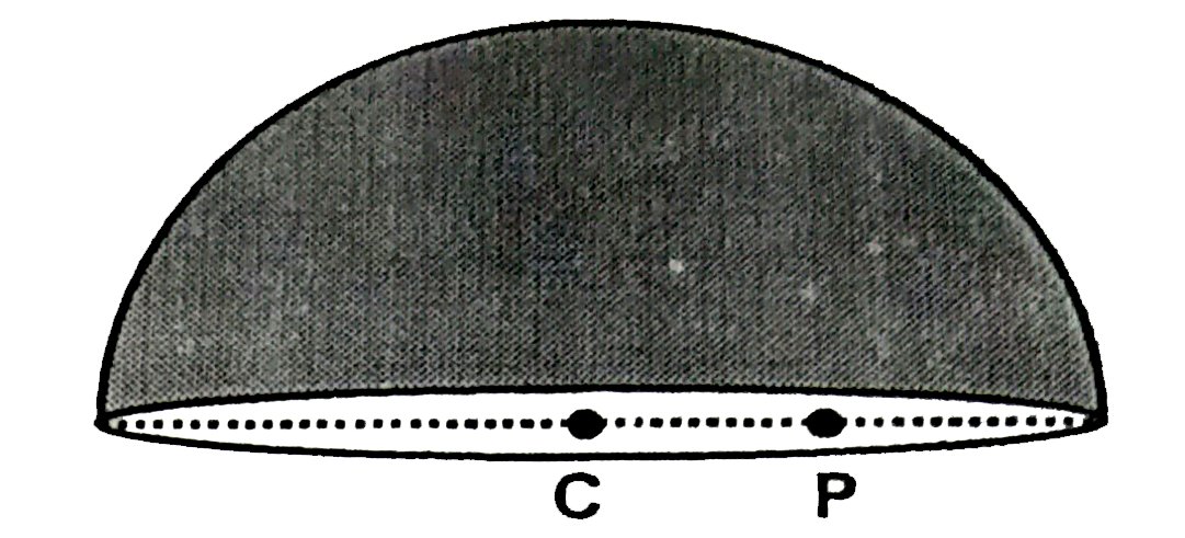
A thin non-conducting hemispherical shell contains a positive charge q on it, which uniformly distributed on the shell. A point P lies on the diameter of shell as show in figure. Then the direction of electric field at the point 'P' is
 A
A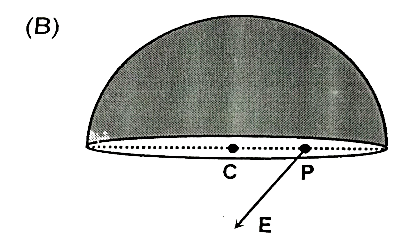 B
B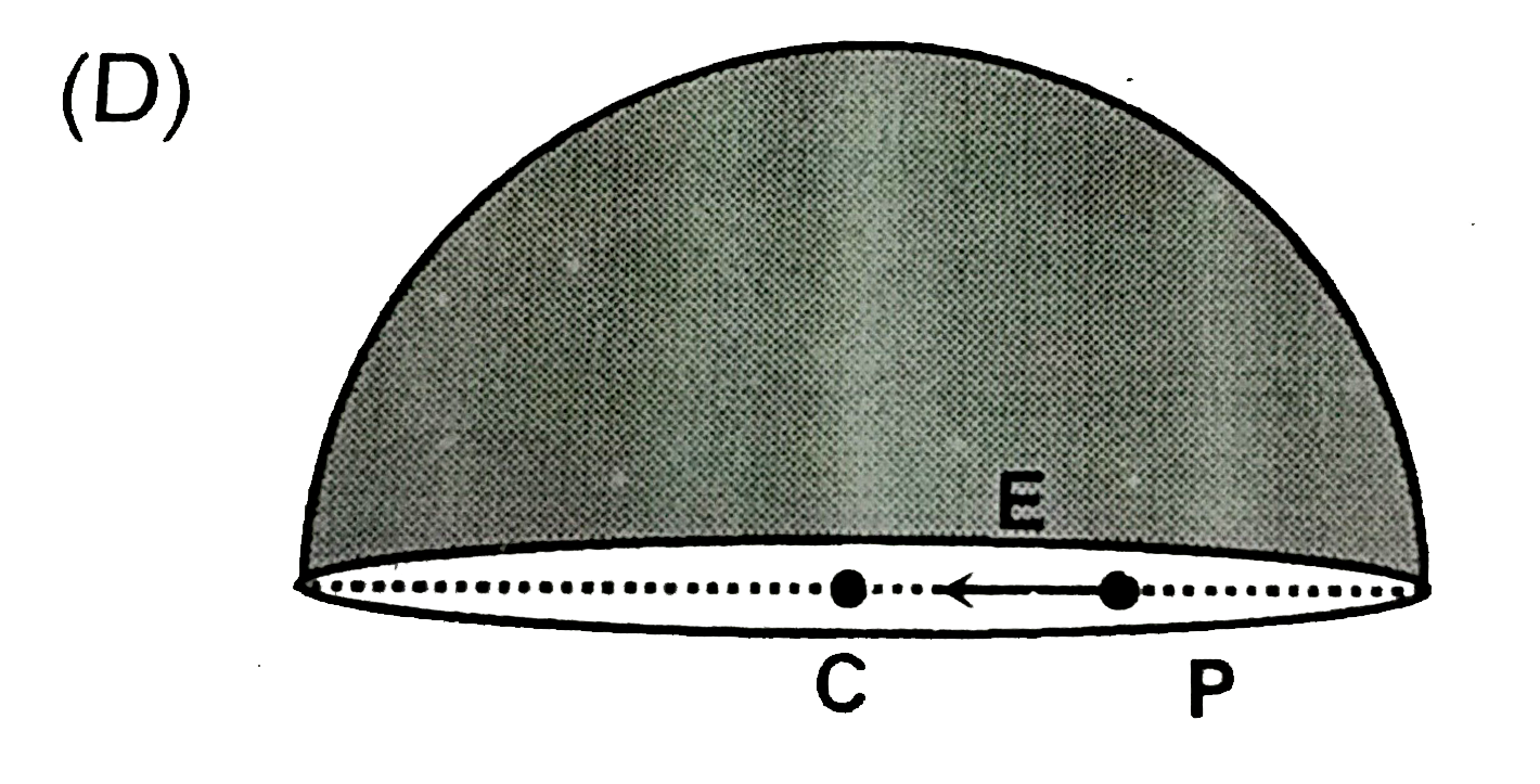 C
C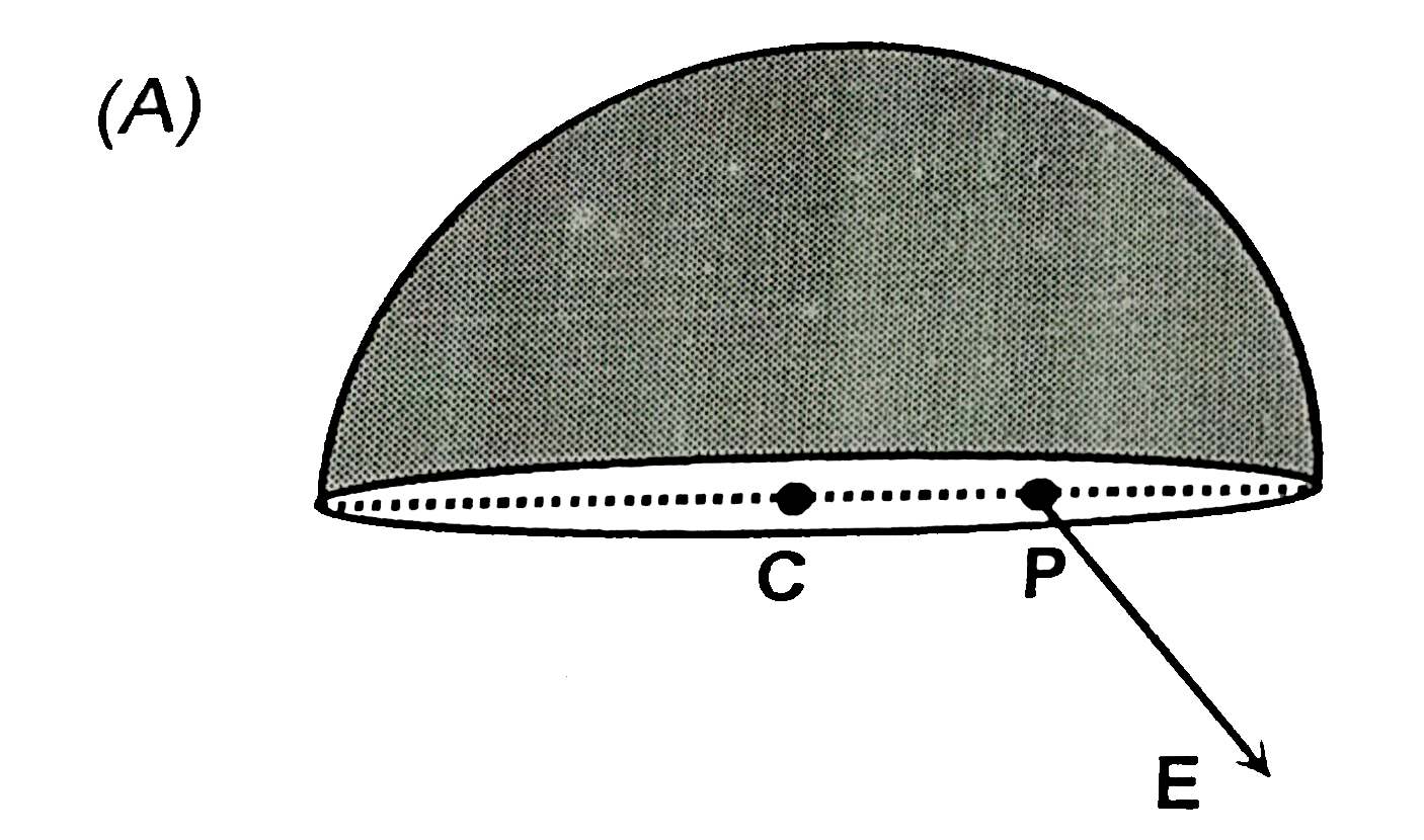 D
D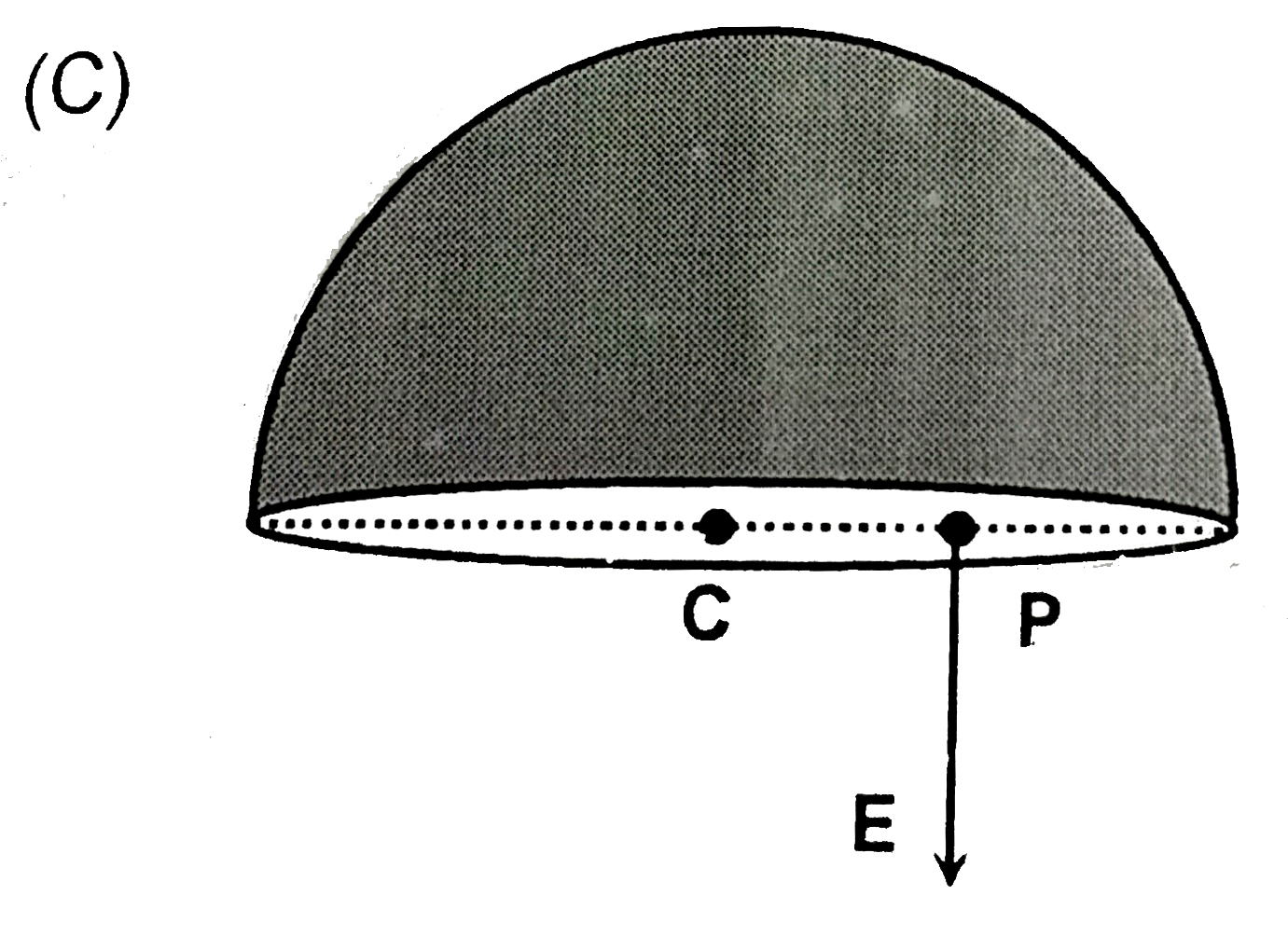
A metallic shell has a point charge 'q' kept inisde its cavity. Which one of the following diagrams correctly represents the electric lines of forces?
A(a)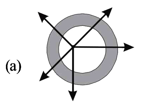 B(b)
B(b)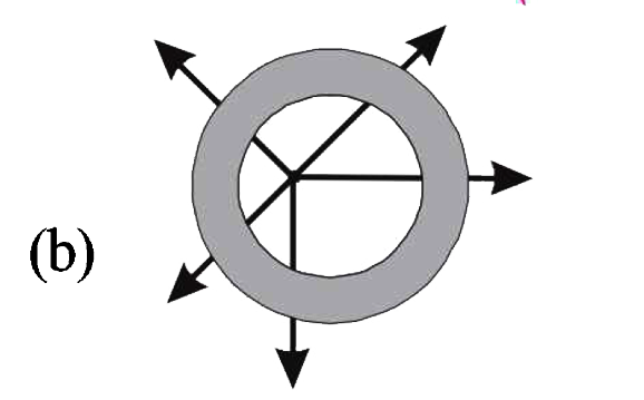 C(c)
C(c)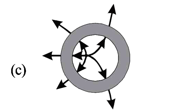 D(d)
D(d)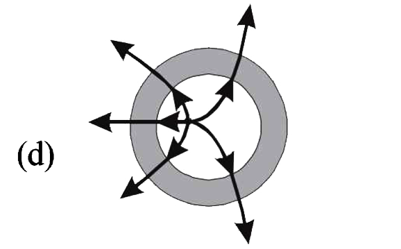
A spherical shell of radius R=1.5cm has a charge q=20μC uniformly distributed over it. The force exerted by one half over the other half is
AzeroB10−2NC500 ND2000 N
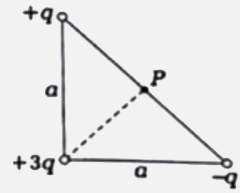
A right isosceles triangle of side a has changes q, 3q and - q arranged on its verticals as shown in the figure. What is the electric potential at P midway between the line connecting the + q and – q charges ?
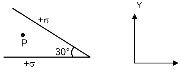
View SolutionThere are two infinite plane sheets each having uniform surface charge density +σC/m2 They are inclined to each other at an angle 30∘as shown in the figure. Electric field at any arbitrary point P is:
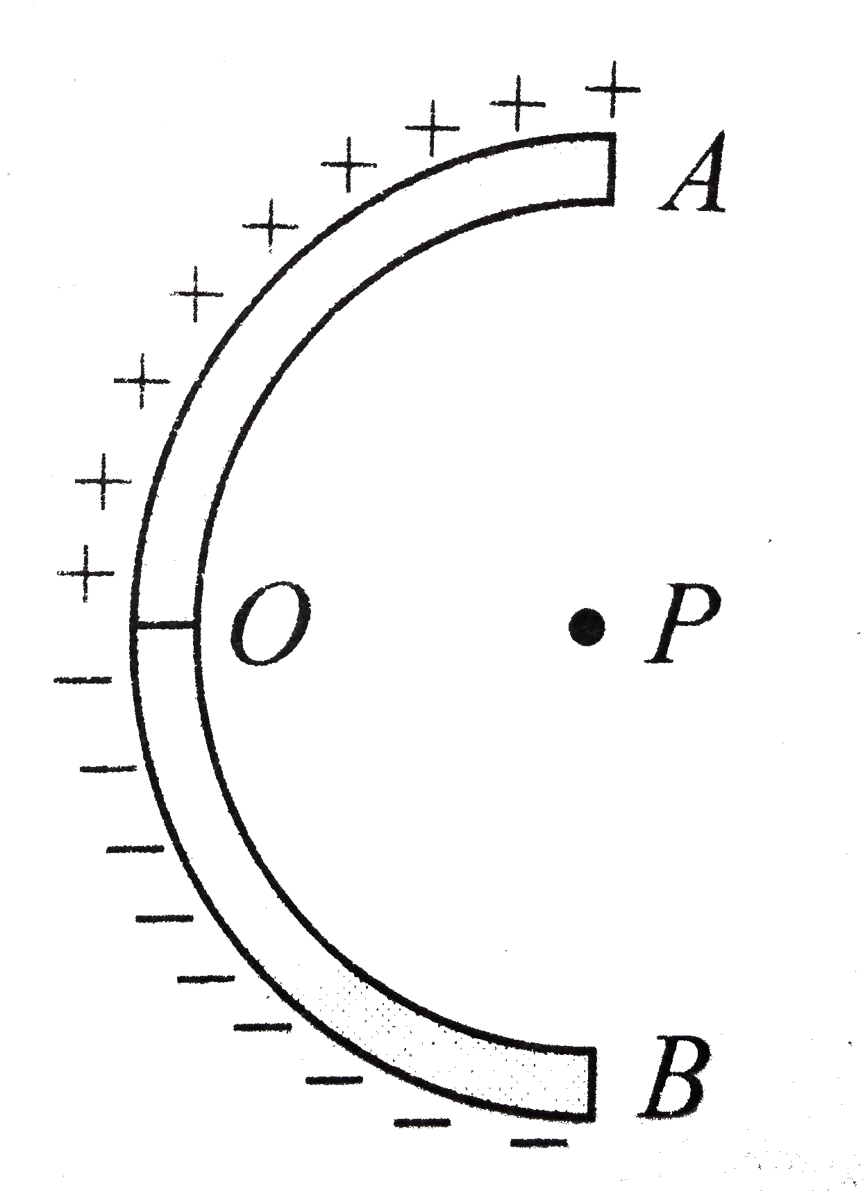
View SolutionA thin glass rod is bent into a semicircle of radius r. A charge +Q is uniformly distributed along the lower half, as shown in fig. The electric field E at P, the center of the semicircle, is
View SolutionTwo charge +q1 and +q2 placed on x-axis at posiution A and B as shown in figure. Which graph best represent potential as a function of distance r from charge q1

View SolutionConsider the situation shown in the figure of the previous problem. Suppose the wire connecting O and C has zero resistance but the circular loop has a resistance R uniformly distributed along its length. The rod OA is made to rotate with a uniform angular speed (ω) as shown in the figure. Find the current in the rod when −AOC=90∘
View Solution
