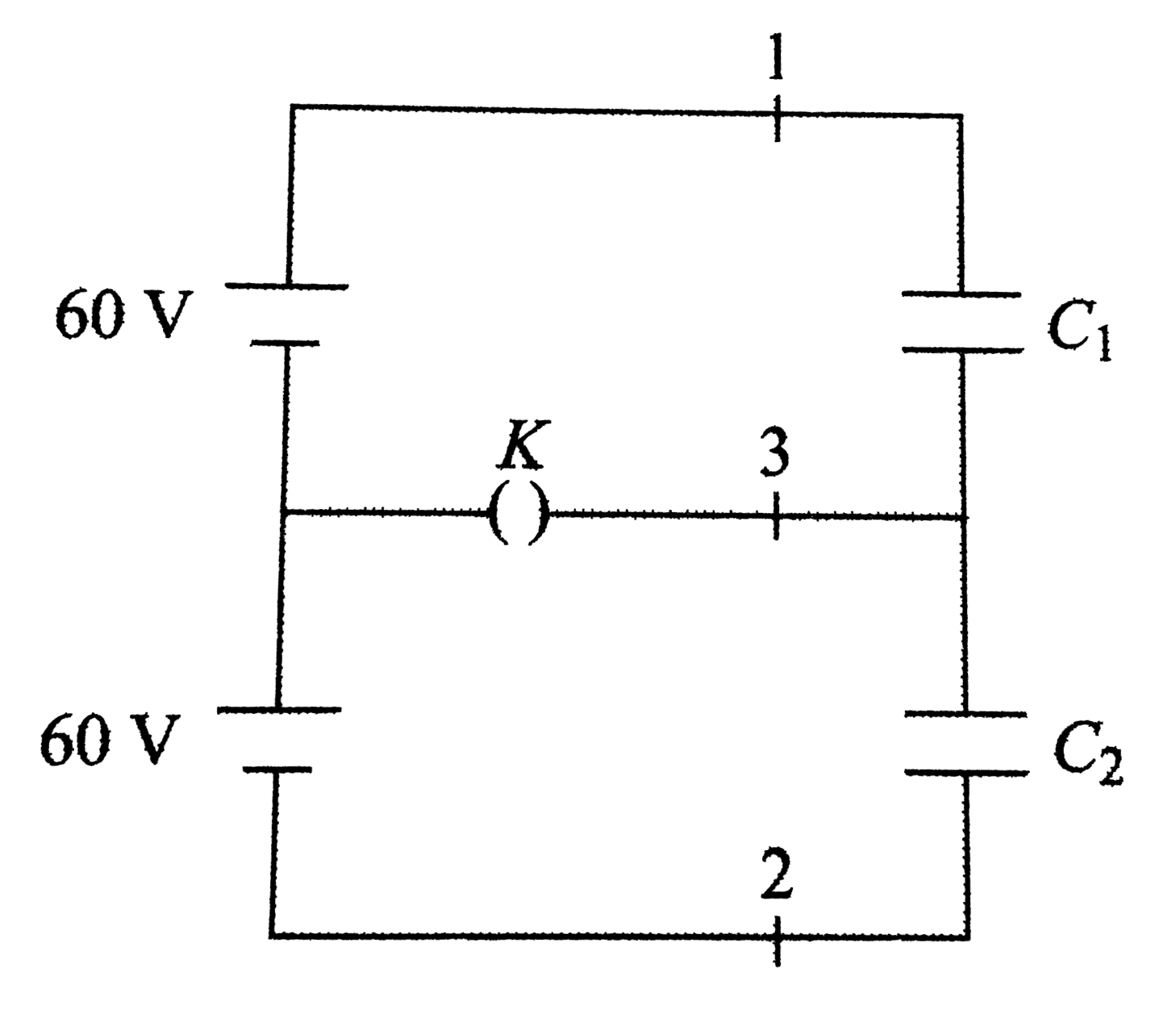
In the circuit shoenin figure 6.17 the emf of each better is 60 V, and the capacitances of the capacitors are C1=3μF and 2μF. Find the charges which will flow after the switch is colosed through the wires 1,2 and 3 n the directions indicated by the arrows. 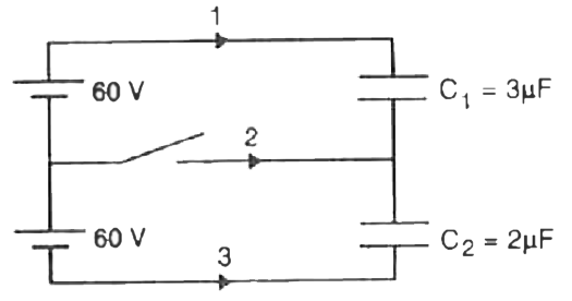
The correct Answer is:q1=+36μC,q2=−60μC,q3=+24μC
Step by step video, text & image solution for In the circuit shoenin figure 6.17 the emf of each better is 60 V, and the capacitances of the capacitors are C_(1)=3muF and 2muF. Find the charges which will flow after the switch is colosed through the wires 1,2 and 3 n the directions indicated by the arrows. by Physics experts to help you in doubts & scoring excellent marks in Class 12 exams.
Topper's Solved these Questions
Similar Questions
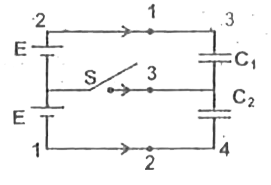
In the circuit shown, the emf of each battery is E. Find the charges that will flow when the switch S is closed, through sections 1, 2 and 3 in the directions indicated by the arrows.
 View Solution
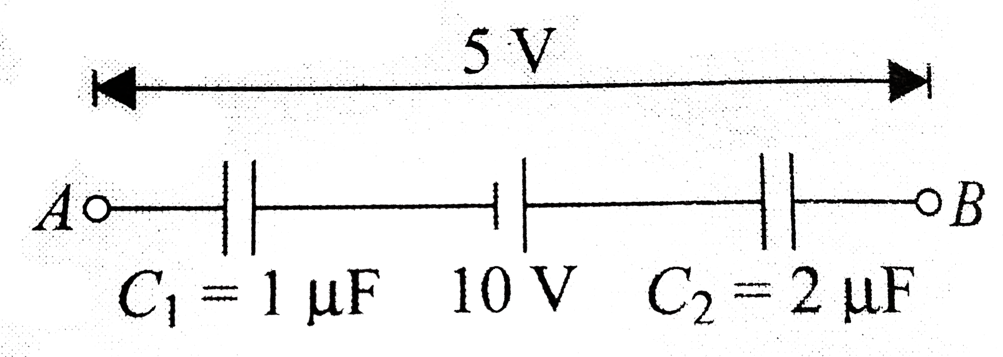
A circuit has section AB as shown in The emf of the cell is 10V, and the capacitors have capacitances C1=1μF and C2=2μF.
 .View Solution
Knowledge Check
- Question 1 - Select One
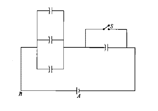
Four capacitors of capacitance 10μF and a battery of 200V are arranged as shown. How much charge will flow through AB after the switch S is closed :
 A6000μCB4500μCC3000μCD4000μC
 - Question 2 - Select One or More
A circuit shown in the figure consists of a battery of emf 10V and two capacitance C1 and C2 of capacitances 1.0μF and 2.0μF respectively. The potential difference VA−VB is 5V
 ACharge on capacitor C1 is equal to charge on capacitor C2BVoltage across capacitor C1 is 5V.CVoltage across capacitor C2 is 10VDEnegry stored in capacitor C1 is two times the enegry stored in capacitor C2.
In the circuit shown , the emf of each battery is 60V and C1=2μF and C2=3μF. Find the charges that will flow through the sections 1,2 and 3 after the Key is closed.
 . View Solution
In the circuit shown the capacitors are C1=15μF,C2=10μFandC3=25μF. Find
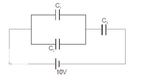
the charge on each capacitor andView SolutionIn the circuit shown the capacitors are C1=15μF,C2=10μFandC3=25μF. Find
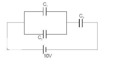
the equivalent capacitance of the circuit.View SolutionIn the circuit shown the capacitors are C1=15μF,C2=10μFandC3=25μF. Find
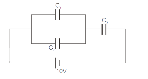
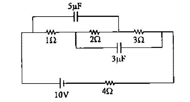
the potential difference across each capacitor.View SolutionIn the circuit shown in figure-3.395, find the charges on capacitors of capacitances 5μFand3μF, in steady state.
 View Solution
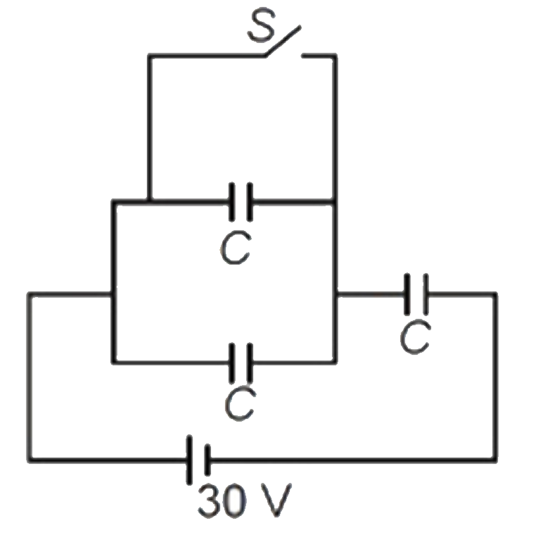
Three capacitors each of capacitance C=2μF are connected with a battery of emf 30 V as shown in the figure . When the switch S is closed , the heat generated in the circuit will be
 View Solution

