A circuit has section AB as shown in The emf of the cell is , and the capacitors have capacitances and .
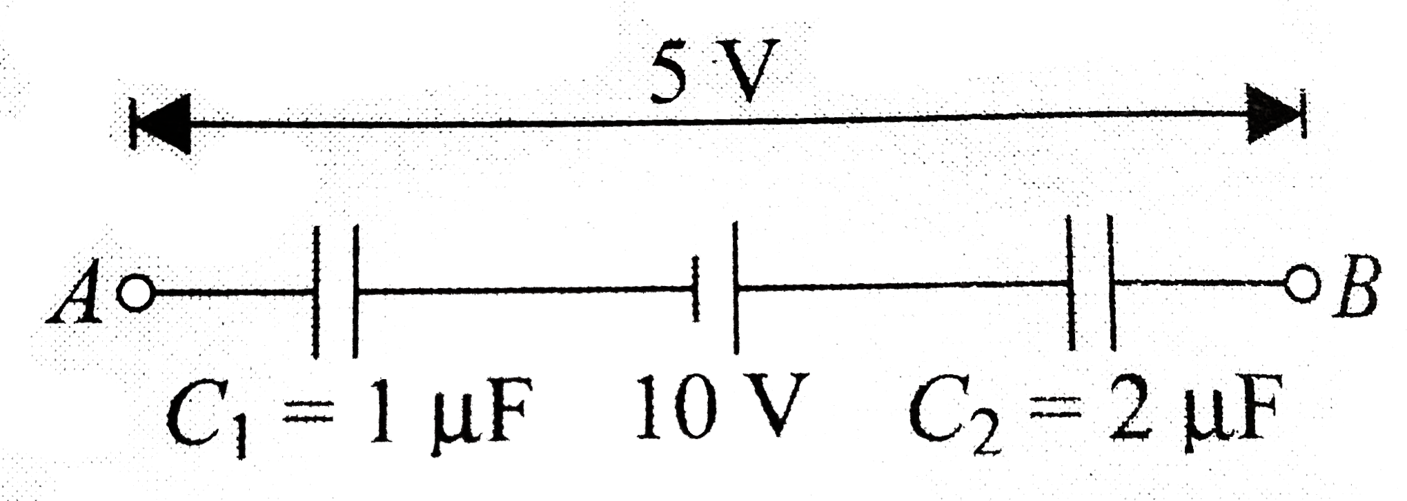 .
.
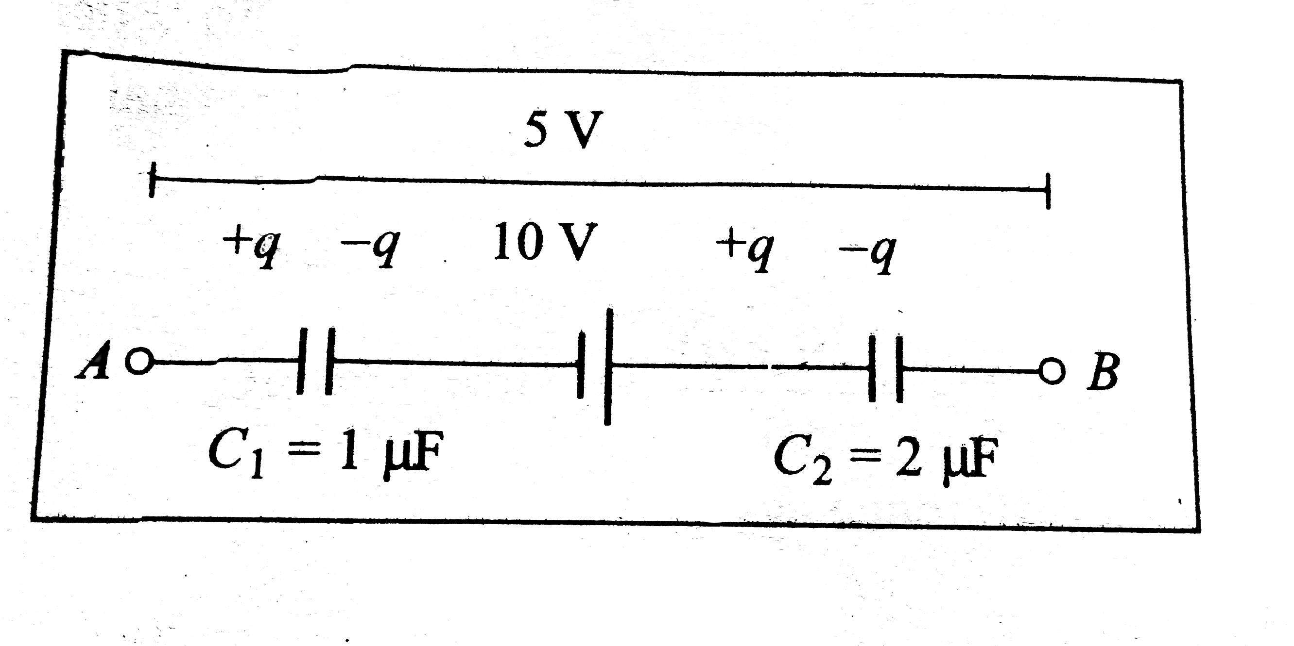
or V_(A) - V_(B) = q + (q)/(2) - 10 muC5 = (3)/(2)q-10q = 10 muC
Topper's Solved these Questions
- BOOK - CENGAGE PHYSICSCHAPTER - CAPACITOR AND CAPACITANCEEXERCISE - Subjective24videos
CAPACITOR AND CAPACITANCE
- BOOK - CENGAGE PHYSICSCHAPTER - CAPACITOR AND CAPACITANCEEXERCISE - Single Correct49videos
CAPACITOR AND CAPACITANCE
- BOOK - CENGAGE PHYSICSCHAPTER - CAPACITOR AND CAPACITANCEEXERCISE - Exercise 4.113videos
CAPACITOR AND CAPACITANCE
- BOOK - CENGAGE PHYSICSCHAPTER - ATOMSEXERCISE - QUESTION BANK40videos
ATOMS
- BOOK - CENGAGE PHYSICSCHAPTER - CENGAGE PHYSICS DPPEXERCISE - subjective type51videos
CENGAGE PHYSICS DPP
Similar Questions
A circuit has section AB as shown in figure. The emf of the source equals E=10V, the capacitor capacitances are equal to C1=1.0μF and C2=2.0μF, and the potential difference VA−VB=5.0V. Find the voltage across each capacitor.
 View Solution
A circuit has a section Ab shown in fig. The emf of the source equals E=10V, the capacitances are equal to C1=1.0μF and C2=2.0μF, and the potential difference φA−φB=5.0V. Find the voltage across each capacitor.
 View Solution
Knowledge Check
- Question 1 - Select One or More
Shows a part of a circuit. If all the capacitors have a capacitance of 2μF, then the
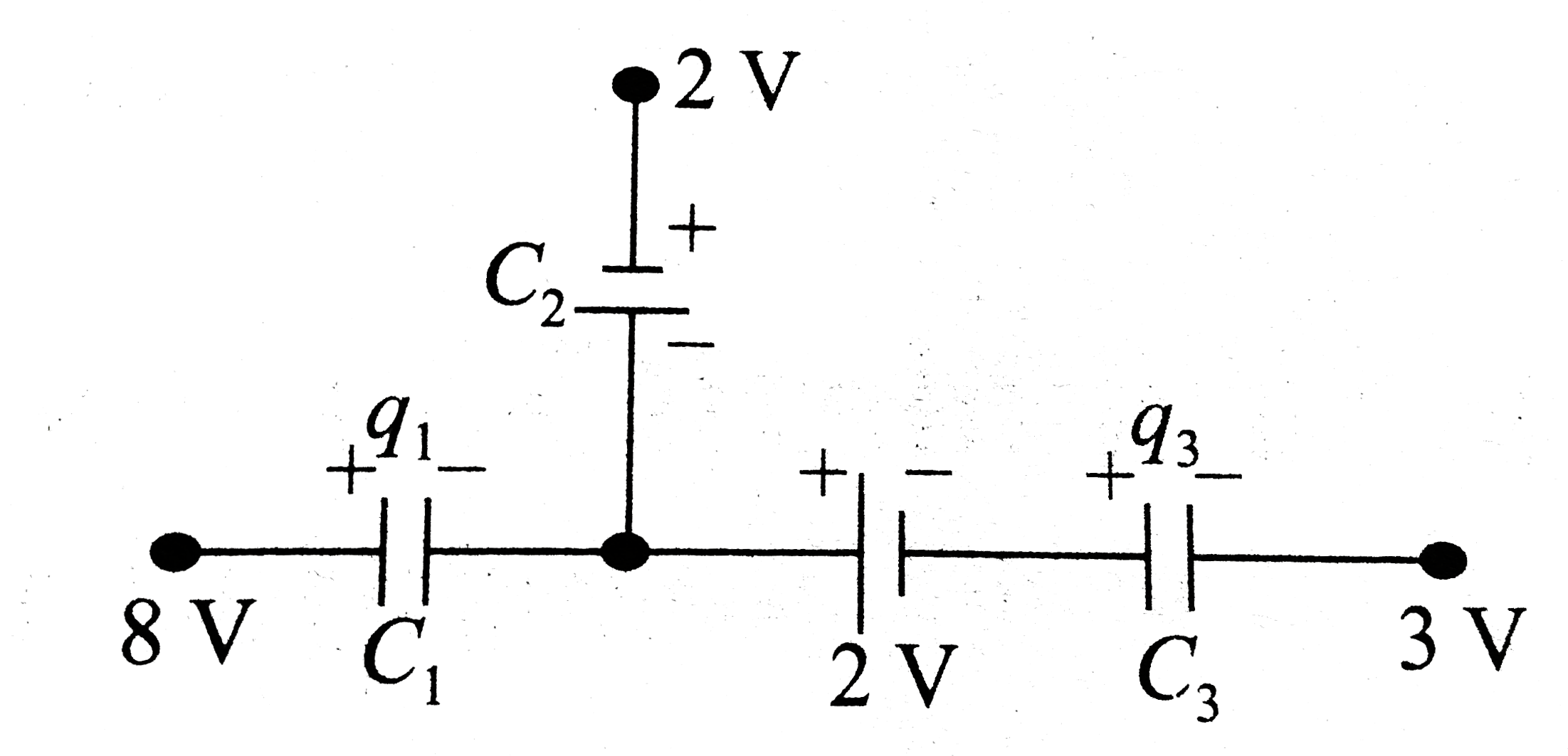 . Acharge on C3 is zeroBcharge on C3 is 12μCCcharge on C1 is 6μCDcharge on C1 in 6μC
 - Question 2 - Select One
In the circuit shown in, C=6μF. The charge stored in the capacitor of capacity C is
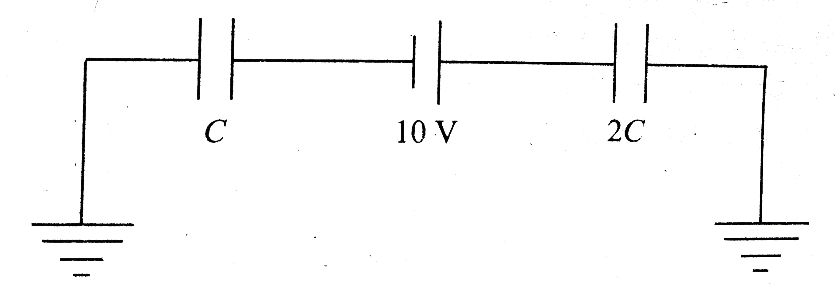 . AzeroB90μCC40μCD60μC
 - Question 3 - Select One
In the circuit shown in figure, the charge stored on a capacitor of capacitance 3μF is
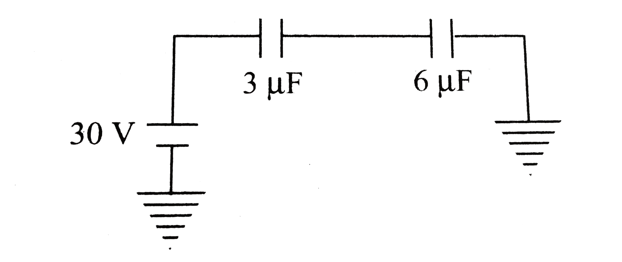 AzeroB40μCC60μCD90μC
In the circuit shoenin figure 6.17 the emf of each better is 60 V, and the capacitances of the capacitors are C1=3μF and 2μF. Find the charges which will flow after the switch is colosed through the wires 1,2 and 3 n the directions indicated by the arrows.
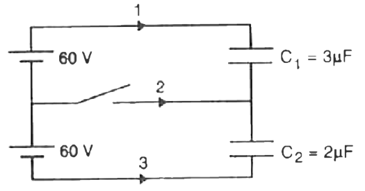 View Solution
A capacitor of capacitance C1=1.0μF charged up to a voltage V=110V is connected in parallel to the teminals of a circuit consisting of two uncharged capacitors connected in series and possessing the capacitances Cs=2.0μF and Cs=3.0μF. What charge will flow through the connecting wires ?
View SolutionA circuit shown in the figure consists of a battery of emf 10V and two capacitance C1 and C2 of capacitances 1.0μF and 2.0μF respectively. The potential difference VA−VB is 5V
 View Solution
A potential of V=3000V is applied to a combination of four initially uncharged capacitors as shown in the figure. Capacitors A, B, C and D have capacitances CA=6.0μF,CB=5.2μF,CC=1.5μFandCD=3.8μF, respectiely. If the battery is disconnected, then potential difference across capacitor B is (approximately)
 View Solution
A circuit has a section AB as shown in the fig. With E =10V. C1=1.0μF,C2=2.0μF and the potential difference VA–VB=5V. The voltage across C1 is :
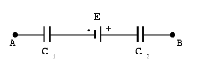 View Solution

