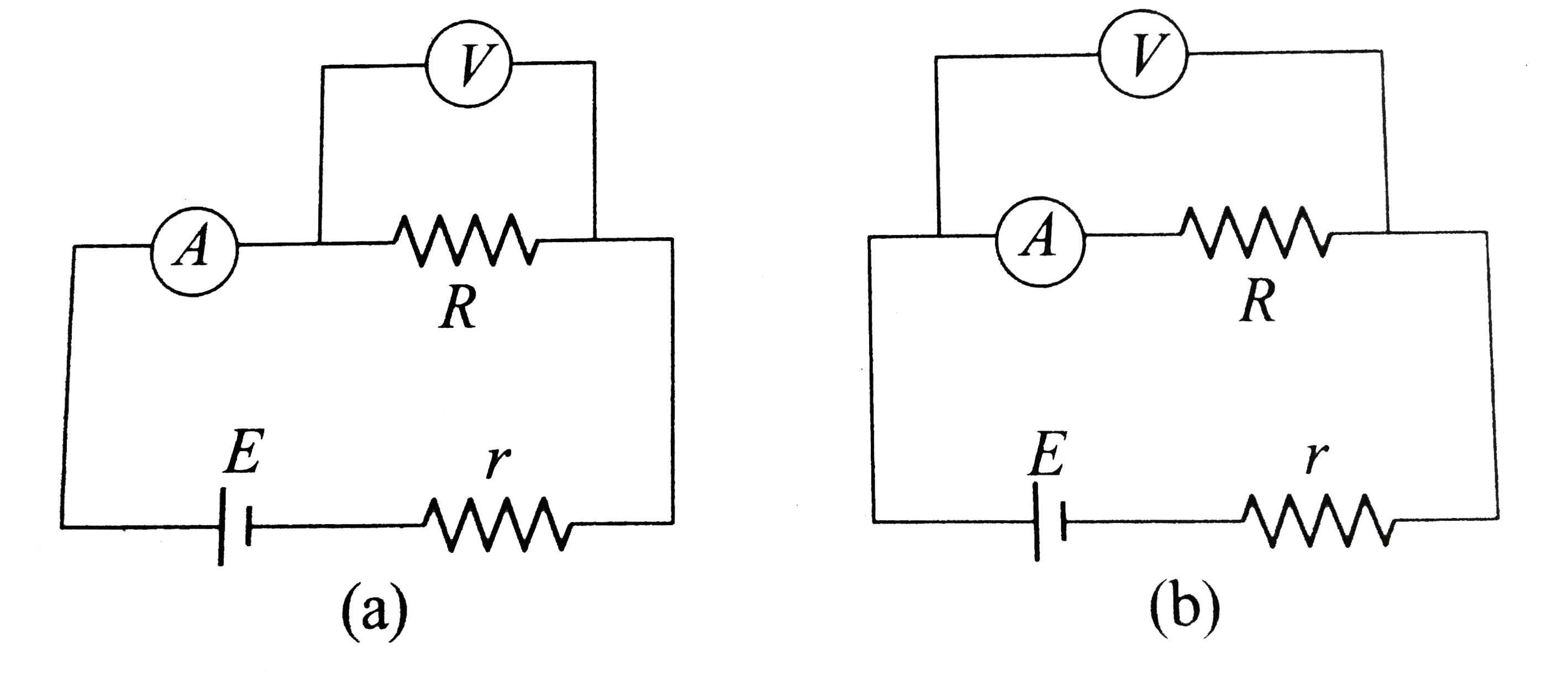
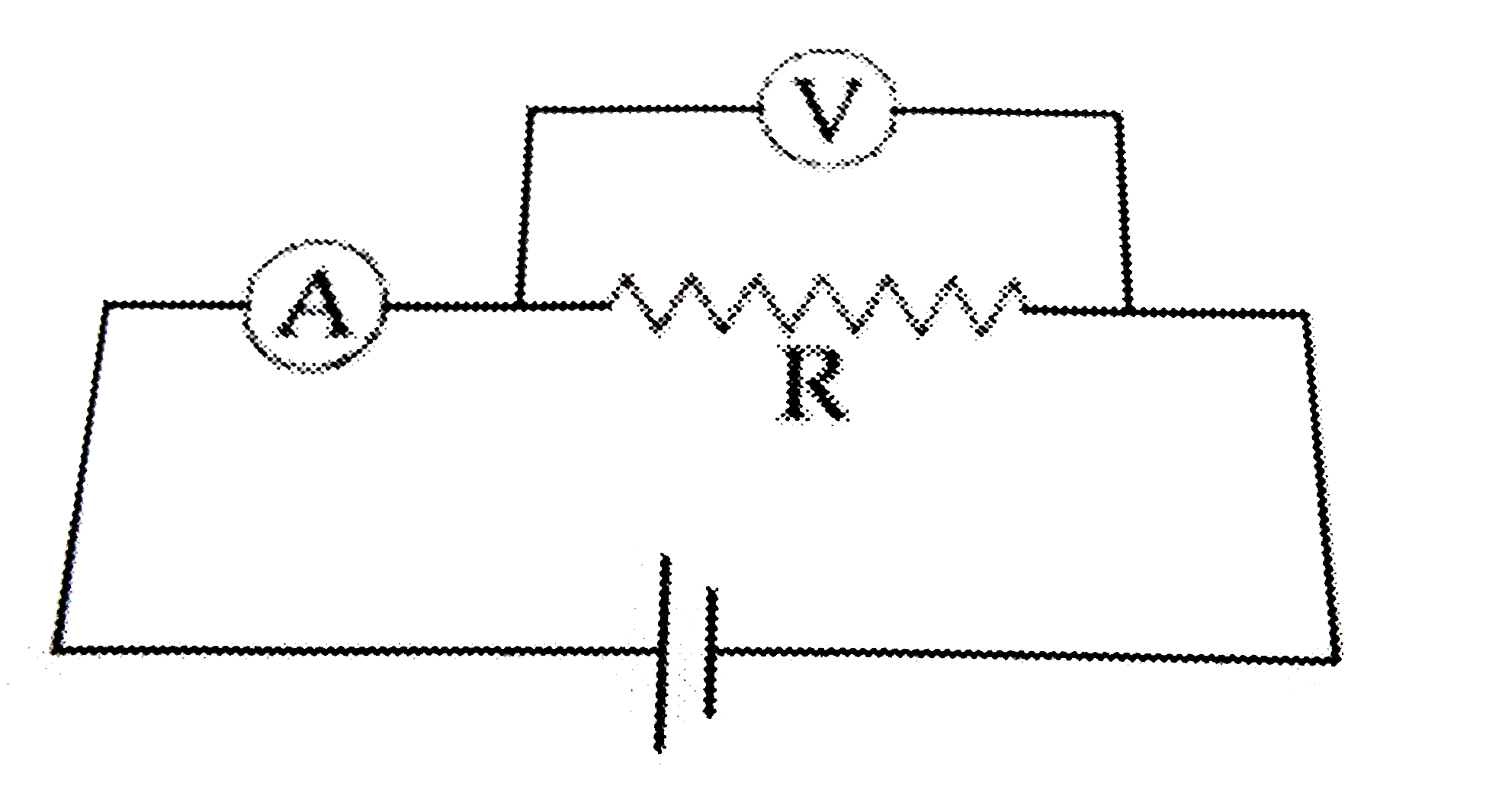
Which of the following circuits gives the correct value of resistance, when computed by using R=(V/I) where V and I are voltmeter and ammeter reading, respectively? The meters are not ideal.
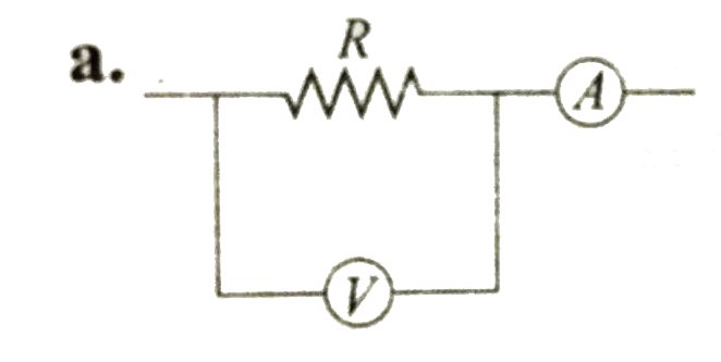
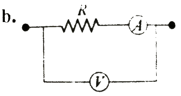
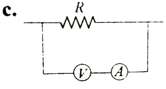
none of these
The correct Answer is:D
d. In first two circuit diagrams, corrections have to be made while
third one is absolutely wrong. So, none of the circuit diagrams
is giving correct value of R.
Similar Questions
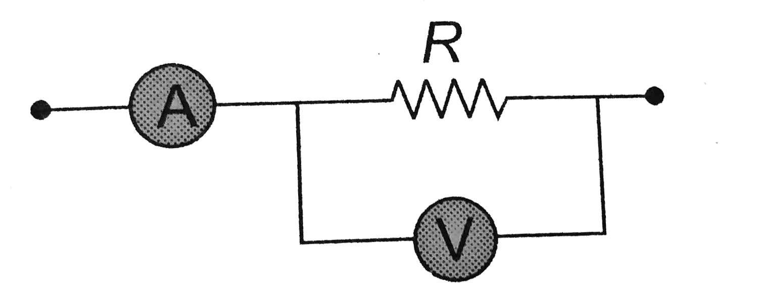
In the circuit shown the reading of ammeter and voltmeter are 4A and 20V respectively. The meters are non ideal, then R ia
View SolutionConsider the two circuits P and Q, shown below, which are used 20 measure the unknown resistance R.

In each case, the resistance is estimated by using Ohm's law Rest=V/I, Where V and I are the readings of the voltmeter and the ammeter respectively. The meter resistances, Rv and RA are such that RA<<R<<Rv. The internal resistance of the battery may be ignored. The absolute error in the estimate of the resistance is denoted by δR=|R=Rest|.
View Solution
Knowledge Check
In the circuit shown the reading of ammeter and voltmeter are 4A and 20V respectively. The meters are non ideal, then R ia
 A5ΩBless than 5ΩCgreater than 5ΩDbetween 4Ω and 5Ω
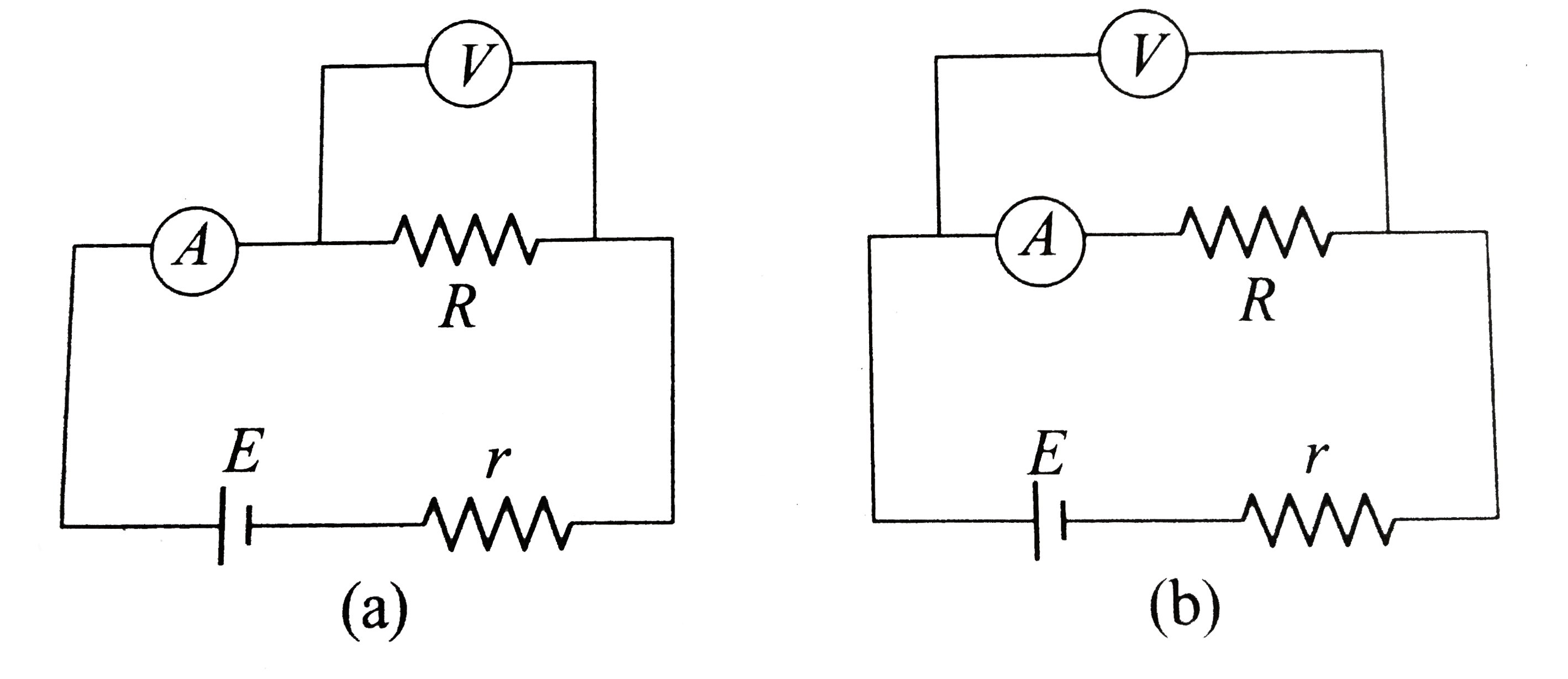
The value of resistance of an unknown resistor is calculated using the formula R=V/I where V and I are the readings of the voltmeter and the ammeter, respectivley. Consider the circuits below. The internal resistances of the voltmeter and the ammeter (RVandRG,respectively) are finite and nonzero.
 ,
,
Let RAandRB be the calculated values in the two cases A and B , respectively.
If the resistance of voltmeter is RV=1kΩ and the percentage error in the measurement of R (the value of R is nearly 10Ω)isAzero in both casesBnonzero but equal in both casesCmore in circuit ADmore in circuit BThe value of resistance of an unknown resistor is calculated using the formula R=V/I where V and I are the readings of the voltmeter and the ammeter, respectivley. Consider the circuits below. The internal resistances of the voltmeter and the ammeter (RVandRG,respectively) are finite and nonzero.
 ,
,
Let RAandRB be the calculated values in the two cases A and B , respectively.
The relation between RA and the actual value of R isAR>RABR<RACR=RBDdependent upon E and r.
The value of resistance of an unknown resistor is calculated using the formula R=V/I where V and I are the readings of the voltmeter and the ammeter, respectivley. Consider the circuits below. The internal resistances of the voltmeter and the ammeter (RVandRG,respectively) are finite and nonzero.
 ,
,
Let RAandRB be the calculated values in the two cases A and B , respectively.
If the resistance of voltmeter is RV=1kΩ and the percentage error in the measurement of R (the value of R is nearly 10Ω)is
View SolutionResistance value of an unknown resistor is calculated using the formula R=VI where V and I be the readings of the voltmeter and the ammeter respectively. Consider the circuits below. The internal resistances of the voltmeter and the ammeter (RvandRGrespectively ) are finite and non zero.
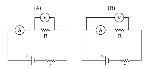
Let RvandRG be the calculated values in the two cases A and B respectively.
If the resistance of voltmeter is Rv=1kΩ and that of ammeter is RG=1Ω the magnitude of the percentage error in the measurement of R (the value of R is nearly 10Ω ) is:
View SolutionResistance value of an unknown resistor is calculated using the formula R=VI where V and I be the readings of the voltmeter and the ammeter respectively. Consider the circuits below. The internal resistances of the voltmeter and the ammeter (RvandRGrespectively ) are finite and non zero.
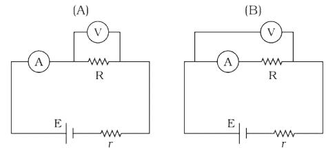
Let RvandRG be the calculated values in the two cases A and B respectively.
The relation between RBand the actual value of R is:
View SolutionThe actual value of resistance R, shown in the figure is 30Ω. This is measured in an experiment as shown using the standard formula R=VI, where V and I are the readings of the voltmeter and ammeter, respectively. If the measured value of R is 5% less, then the internal resistance of the voltmeter is
View SolutionThe actual value of resistance R, shown in the figure is 30Ω. This is measured in an experiment as shown using the standard formula R=VI, where V and I are the readings of the voltmeter and ammeter, respectively. If the measured value of R is 5% less, then the internal resistance of the voltmeter is

View Solution
