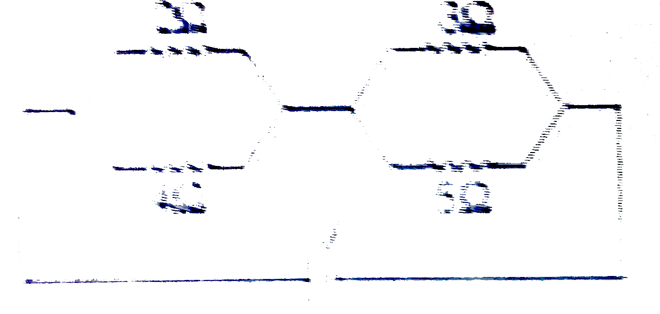
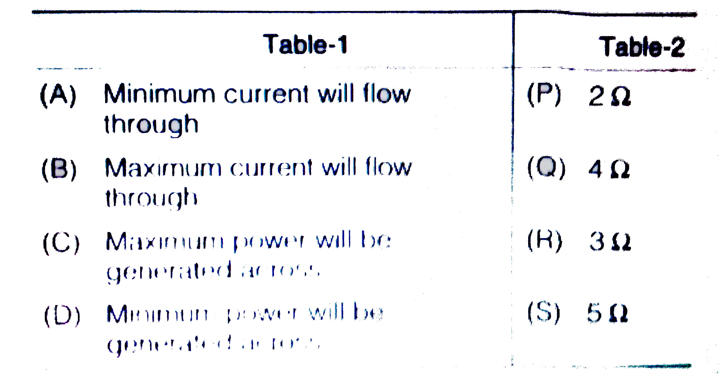
In the circuit shown in figure, if a resistance R connected in parallel with R2, then match following
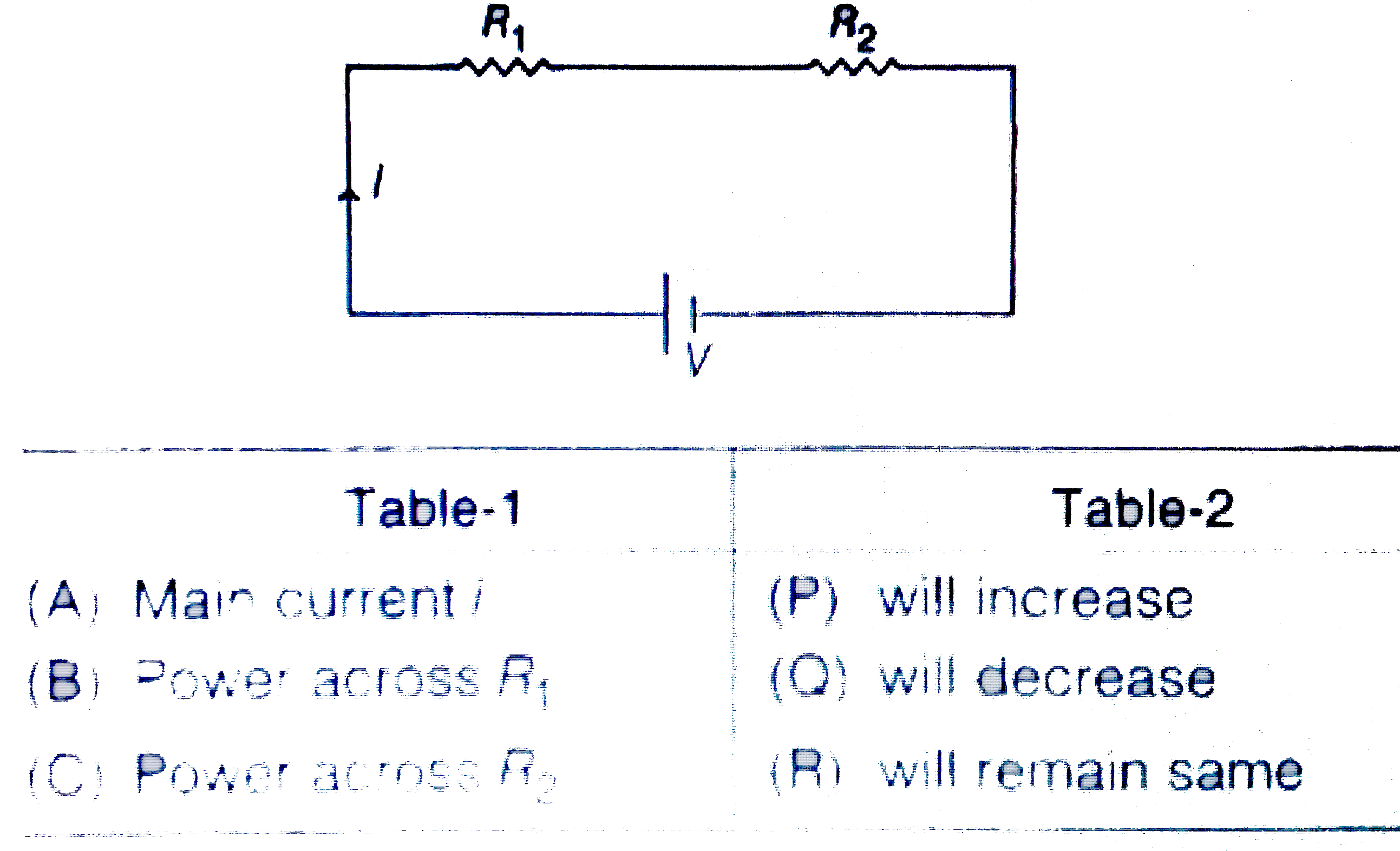
The correct Answer is:(A)P,(B)P,(C)Q,
Step by step video, text & image solution for In the circuit shown in figure, if a resistance R connected in parallel with R_(2), then match following by Physics experts to help you in doubts & scoring excellent marks in Class 11 exams.
Topper's Solved these Questions
Similar Questions
Knowledge Check
- Question 1 - Select One
Assertion : In the circuit shown in figure, battery is ideal. If a resistance R0 is cannected in parallel with R, then power across R will increase.
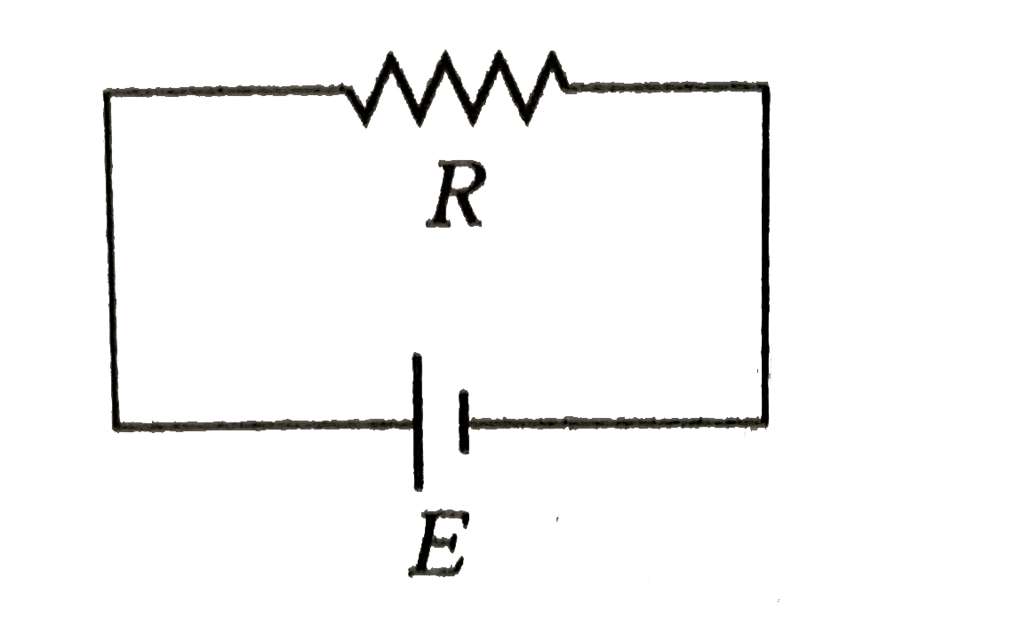
Reason : Current drawn from the battery will increase.AIf both Assertion and Reason are true and Reason is the correct explanation of Assertion.BIf both Assertion and Reason are true and Reason is not correct explanation of Assertion.CIf Assertion is true but Reason is false.DIf Assertion is false but Reason is true. - Question 2 - Select One or More
In the circuit shown in figure resistance of each wire is r. Net resistance across
 Aa and b is 1325rBb and c is 1950rCd and e is 725rDf and g is 1150r
 - Question 3 - Select One
In the circuit shown, n identical resistors R are connected in parallel (n gt 1) and the combination is connected in series to another resistor R0. In the adjoining circuit n resistors of resistance R are all connected in series along with R0–
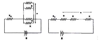
The batteries in both circuits are identical and net power dissipated in the n resistors in both circuits is same. The ratio R0/R isA1BnCn2D1/n
In the circuit shown in figure, match the match the following
 View Solution
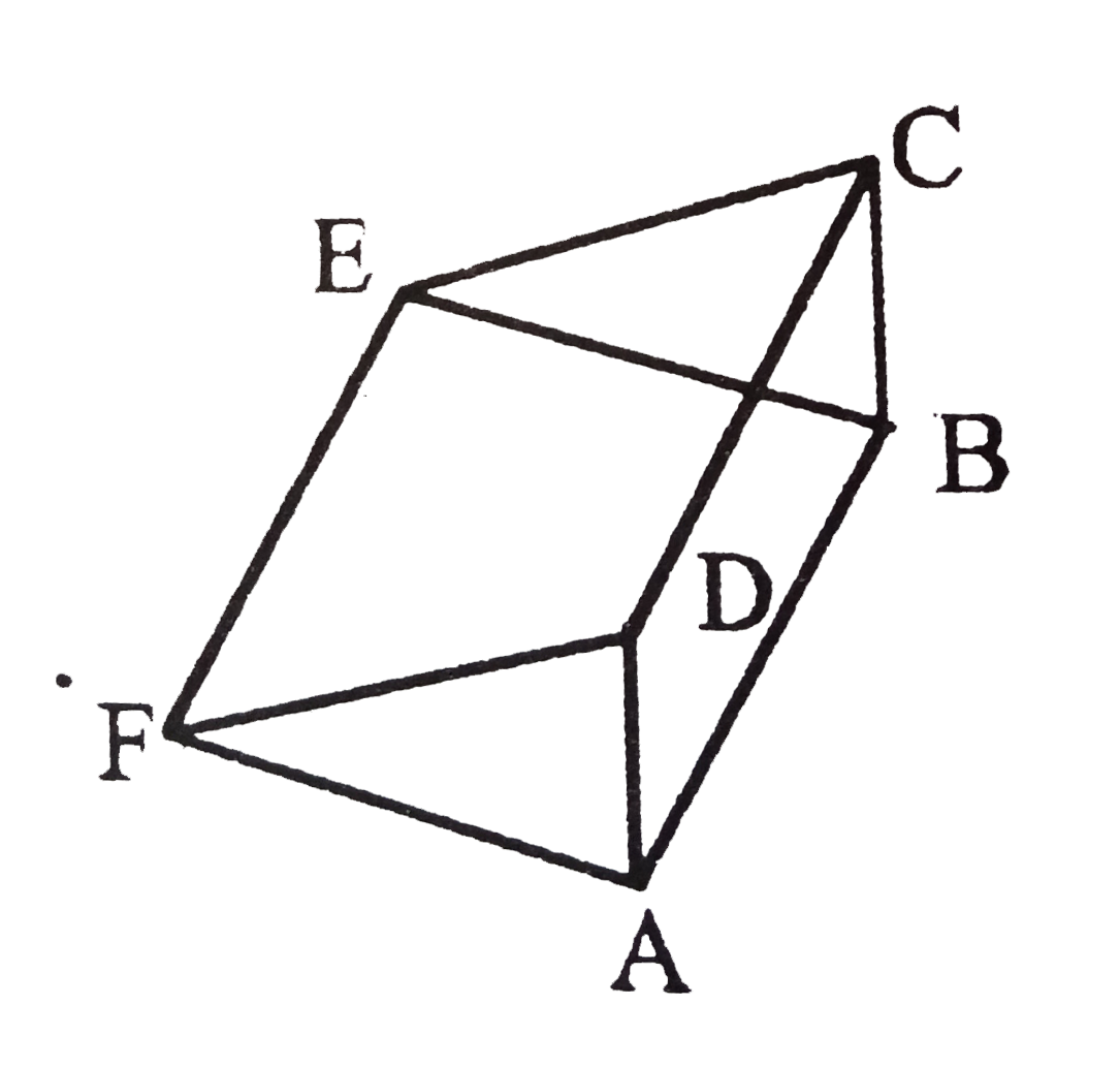
In the circuit shown in figure, all wires have equal resistance r. Find the equivalent resistance between A and B
 View Solution
In the circuit shown in the given figure, the resistances R1andR2 are respectively
 View Solution
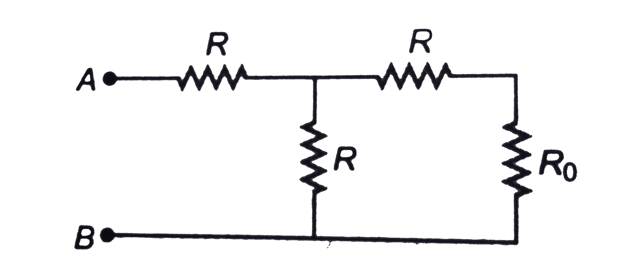
In the circuit shown in figure the total resistance between points A and B is R0. The value of resistance R is
 View Solution
In the circuit shown in the figure (A), R3 is a variable resistance
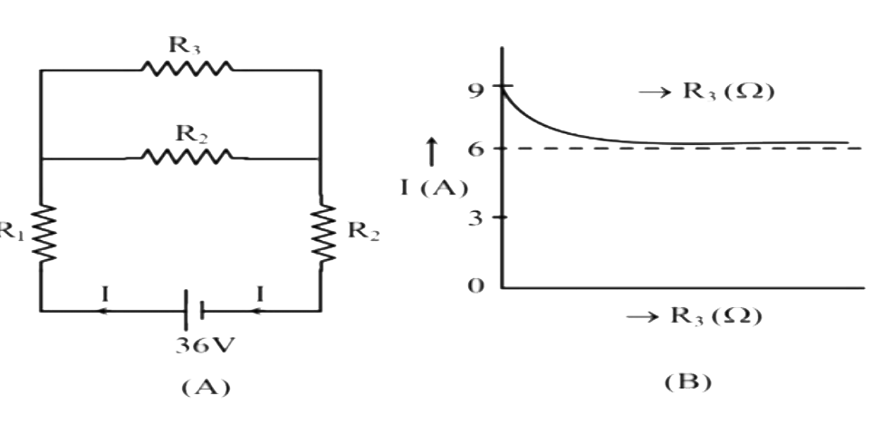
As the value R3 is changed, current I though the cell varies as shown. Obvioulsy, the variation is asymptotic, i.e. I→6A as R3→∞. Resistance R1andR2 are, respectivelyView Solution

