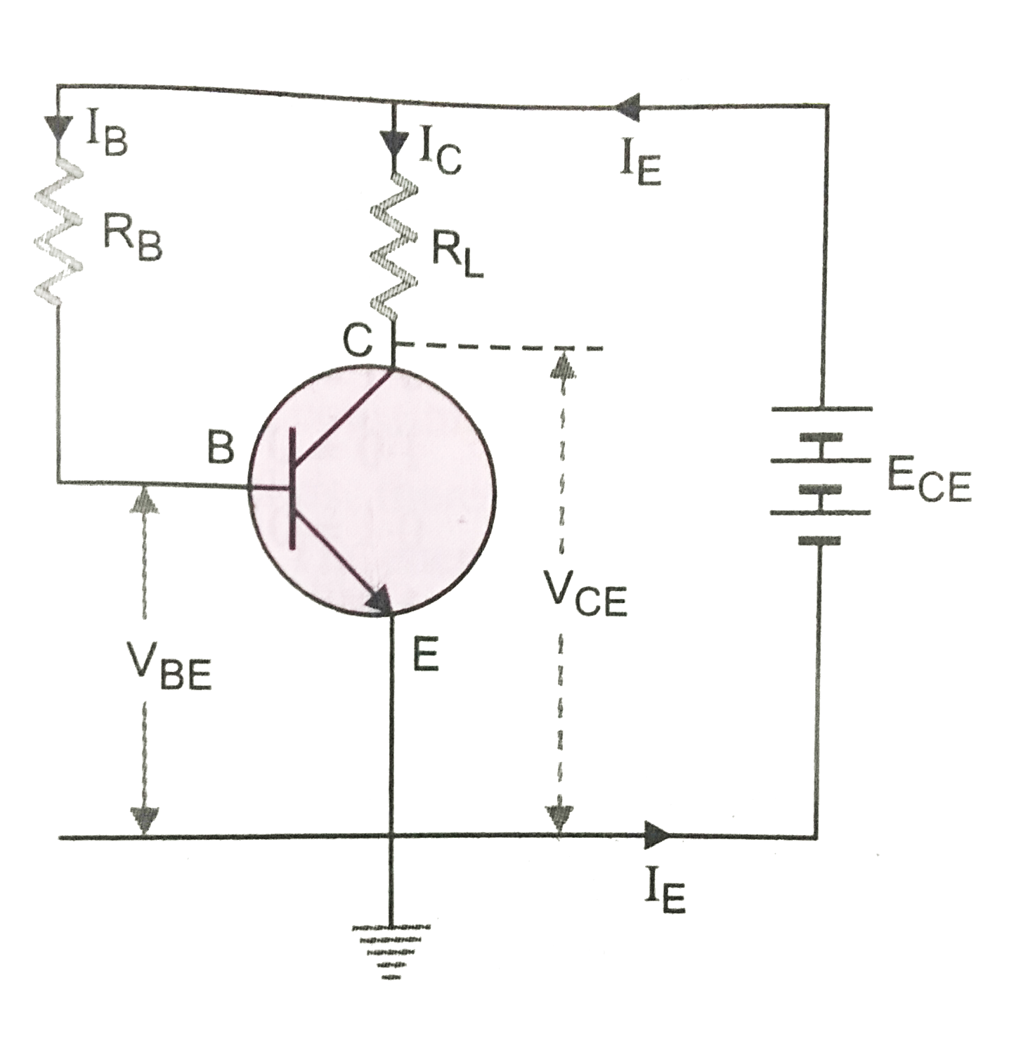
In the circuit shown in fig the base current IB=5.0μA, base resistor RB=1.0MΩ collector resistor Rc=1.0kΩ the collector current IC=5.0mA and the d.c. voltage in the collect circuit VCC=6.0V. (i) Can this circuit be used as an ampifier? (ii) What happens if the resistance RC is 400Ω and IB,IC and iC and RB remain same as above?
The correct Answer is:(i) No (ii) Can be used as ampifier
Similar Questions
In the circuit shown in fig., the base current IB is 10μA and the collector current is 5.2mA. (a) Can this transistor circuit be used as an amplifier? (b) What happen if the resistance RC is 500Ω and IB,IC and RB remain same as above?
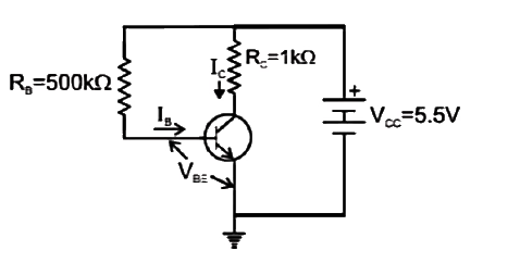
View SolutionIn the circuit shown in Fig. ECE=5.5V,RL=1kΩ,R=500kΩ, the base current, IB is 10μA and collector current, IC=5.2mA. Can this transistor circuit be used as an amplifier?
What happens if the resistance RL is 500Ω and IB,IC and R remain the same as above.

View Solution
Knowledge Check
In the circuit shown in the figure XL=XC2)=R the peck value current i0 is
AAn inductor of 0.103HBAn inductor of 0.25HCA resistance of 6.ΩDA resistance of 100ΩThe collector supply voltage is 6 V and the voltage drop across a resistor of 600 Ω in the collector circuit is 0.6 V, in a circuit of a transistor connected in common emitter mode. What is the base current if the current gain is 20?
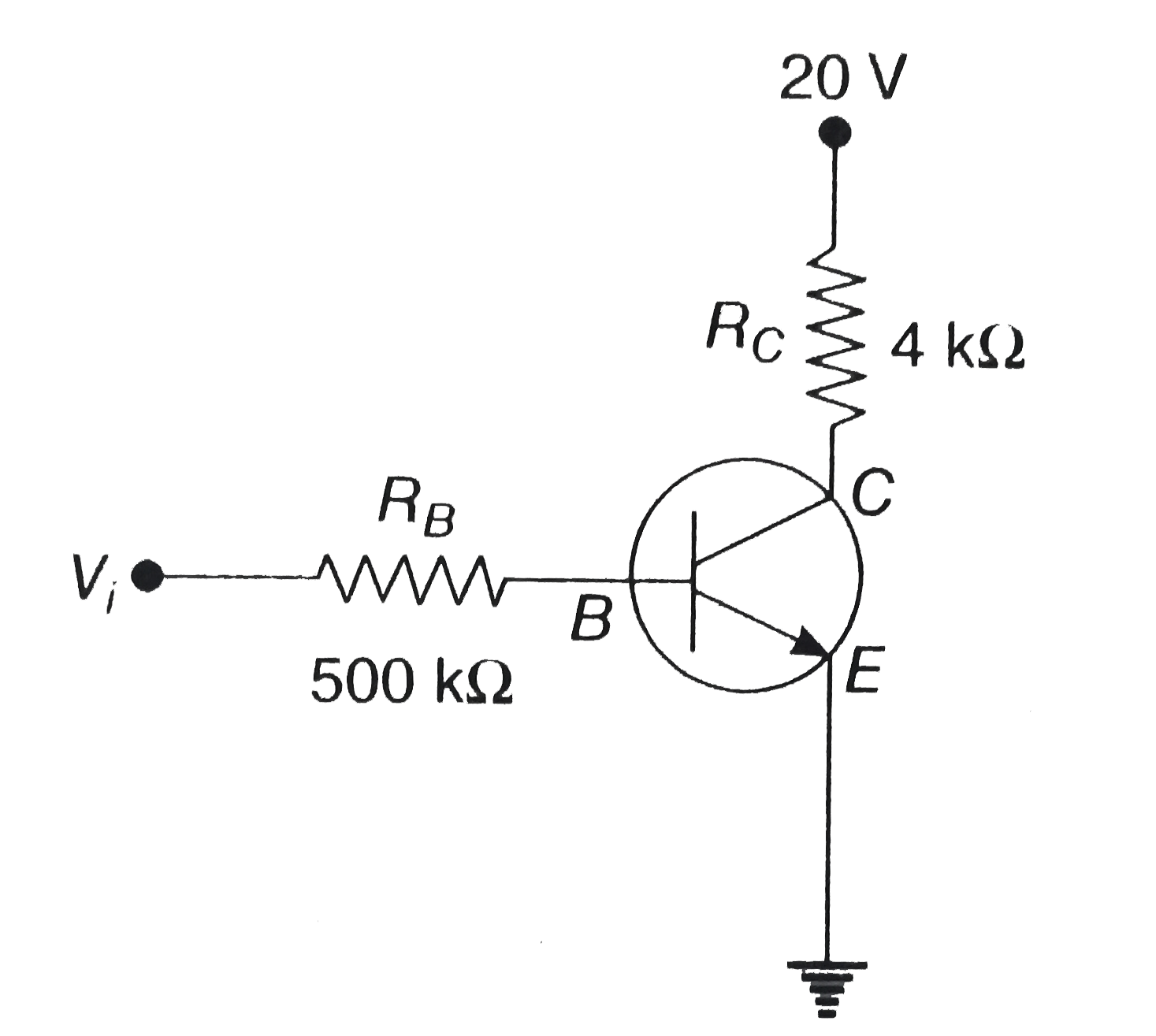
A0.25 mAB0.05 mAC0. 12 mAD0.02 mAIn the circuit shown in the figure, the input voltage Vi is 20V, VBE=0 and VCE=0. The values of IB, IC and β are given by
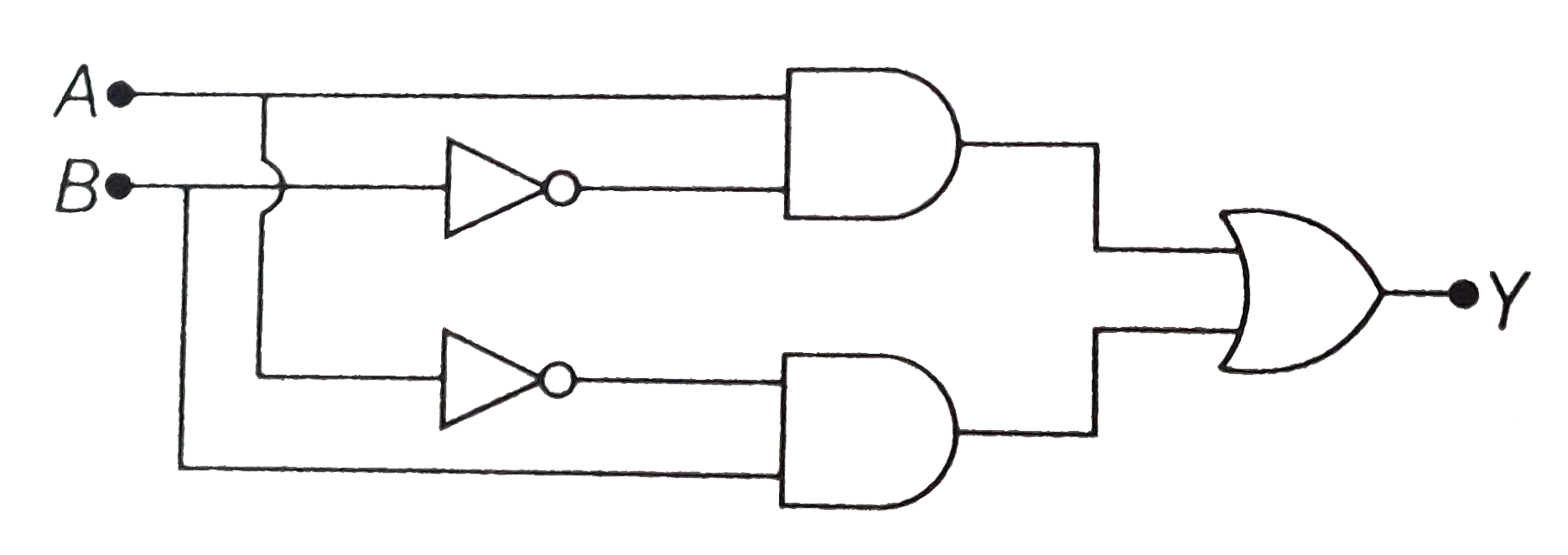
 A¯¯¯¯¯¯¯¯A.B+A.BBA.¯¯¯B+¯¯¯A.BC¯¯¯¯¯¯¯¯A.BD¯¯¯¯¯¯¯¯¯¯¯A+B
In the circuit shown in figure,the base current IB is 10μA and the collector current is 5.2 mA . The voltage (VBE) across the base and emitter is

View SolutionIn the circuit shown in figure,the base current IB is 10μA and the collector current is 5.2 mA . The voltage (VBE) across the base and emitter is

View SolutionIn the circuit shown in the figure XL=XC2)=R the peck value current i0 is
View SolutionIn a transistor connected in a common emitter mode it has, Rc=4kΩ,Ri=1kΩ,Ic=1mAandIb=20μA. Find the voltage gain.
View SolutionIn the circuit shown in the figure, the input voltage Vi is 20V,VBE=0 and VCE=0. The values of IB,IC and β are given by:

View Solution
