In the circuit shown in the figure XL=XC2)=R the peck value current i0 is
a.An inductor of 0.103H
b.An inductor of 0.25H
A resistance of 6.Ω
A resistance of 100Ω
The correct Answer is:A
To solve the problem step by step, we need to analyze the given circuit conditions and apply the relevant formulas for alternating current circuits.
Step 1: Understand the given conditions
We are given that:
- XL=XC2=R
From this, we can derive:
- XL=R
- XC=2R
Step 2: Calculate the impedance Z
The total impedance Z in an AC circuit with resistance R, inductive reactance XL, and capacitive reactance XC can be calculated using the formula:
Z=√R2+(XL−XC)2
Substituting the values we have:
Z=√R2+(R−2R)2
Z=√R2+(−R)2
Z=√R2+R2=√2R2=R√2
Step 3: Calculate the peak current I0
The peak current I0 can be calculated using Ohm's law for AC circuits:
I0=V0Z
Substituting the expression for Z:
I0=V0R√2
Step 4: Simplify the expression
To express I0 in a more manageable form, we can rewrite it as:
I0=V0√22R
Conclusion
Thus, the peak value of the current I0 is:
I0=V0√22R
We are given that:
- XL=XC2=R
From this, we can derive:
- XL=R
- XC=2R
The total impedance Z in an AC circuit with resistance R, inductive reactance XL, and capacitive reactance XC can be calculated using the formula:
Z=√R2+(XL−XC)2
Substituting the values we have:
Z=√R2+(R−2R)2
Z=√R2+(−R)2
Z=√R2+R2=√2R2=R√2
The peak current I0 can be calculated using Ohm's law for AC circuits:
I0=V0Z
Substituting the expression for Z:
I0=V0R√2
To express I0 in a more manageable form, we can rewrite it as:
I0=V0√22R
Thus, the peak value of the current I0 is:
I0=V0√22R
Similar Questions
In the L-C-R circuit as shown in figure,
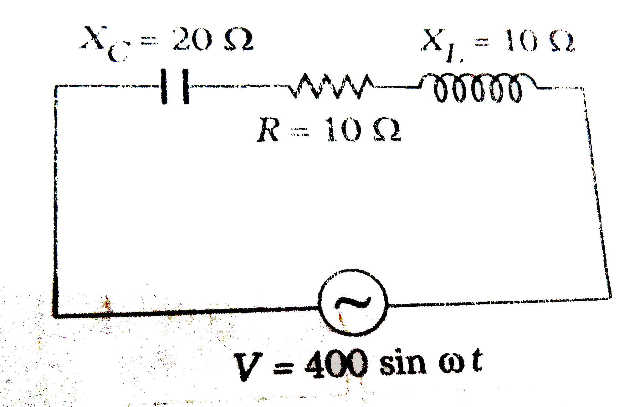
View SolutionIn the circuit shown in figure value of VR is
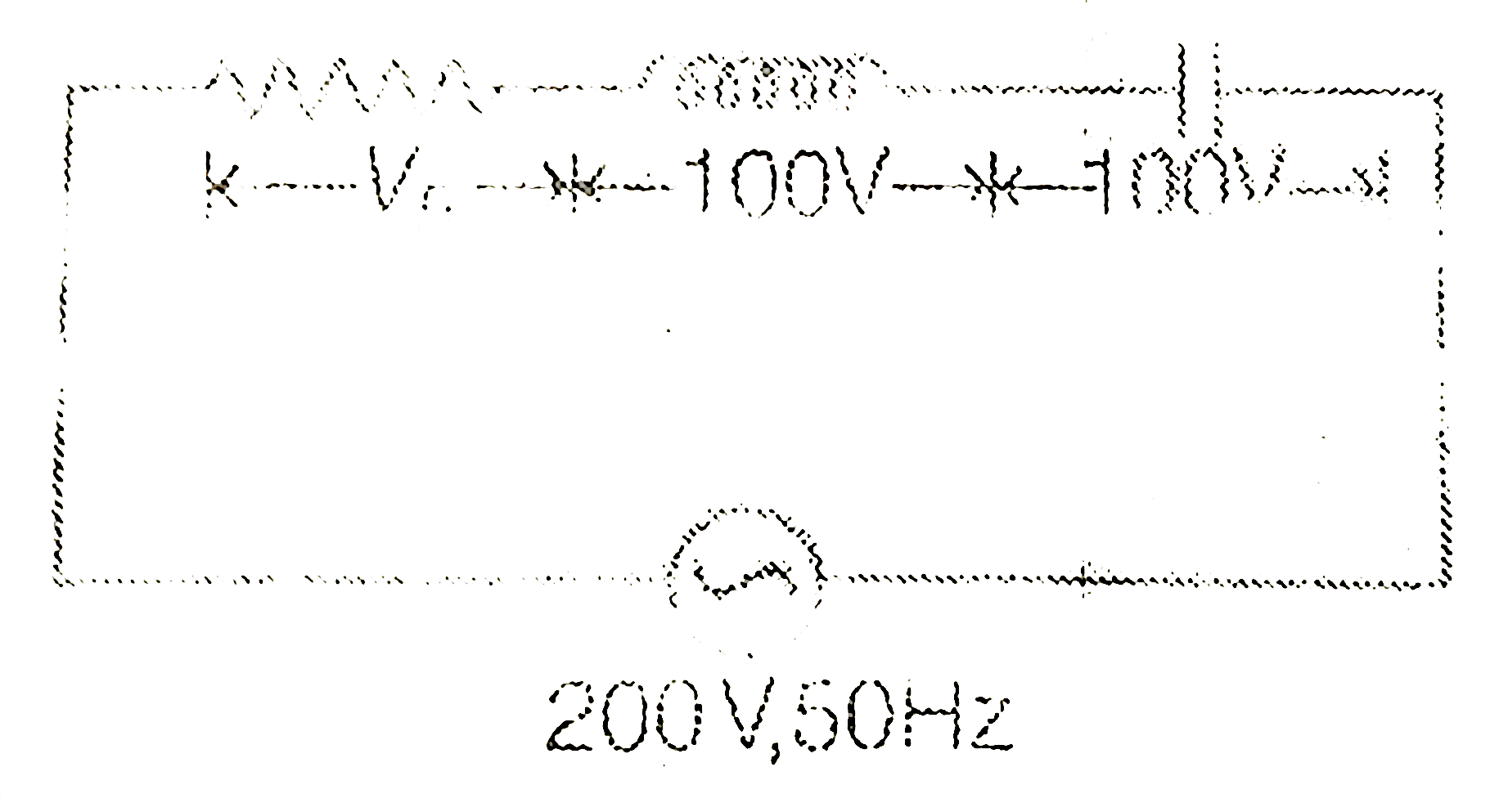
View SolutionIn the circuit shown, the currents i1 and i2 are
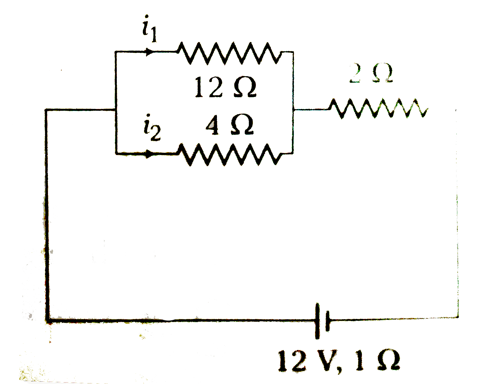
View SolutionIn the circuit shown in the figure The steady state currents i1andi2 in the coils after the switch S is closed are
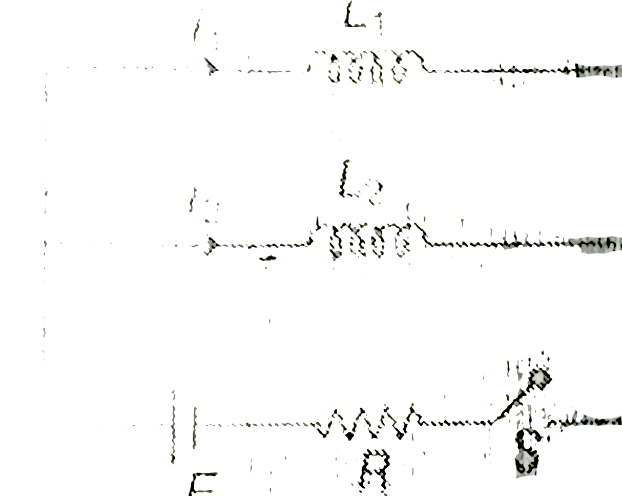
View SolutionIn the circuit shown in figure the current through
View SolutionIn the circuit shown in the figure, the current through the
View SolutionIn the circuit shown in the figure
 .
.
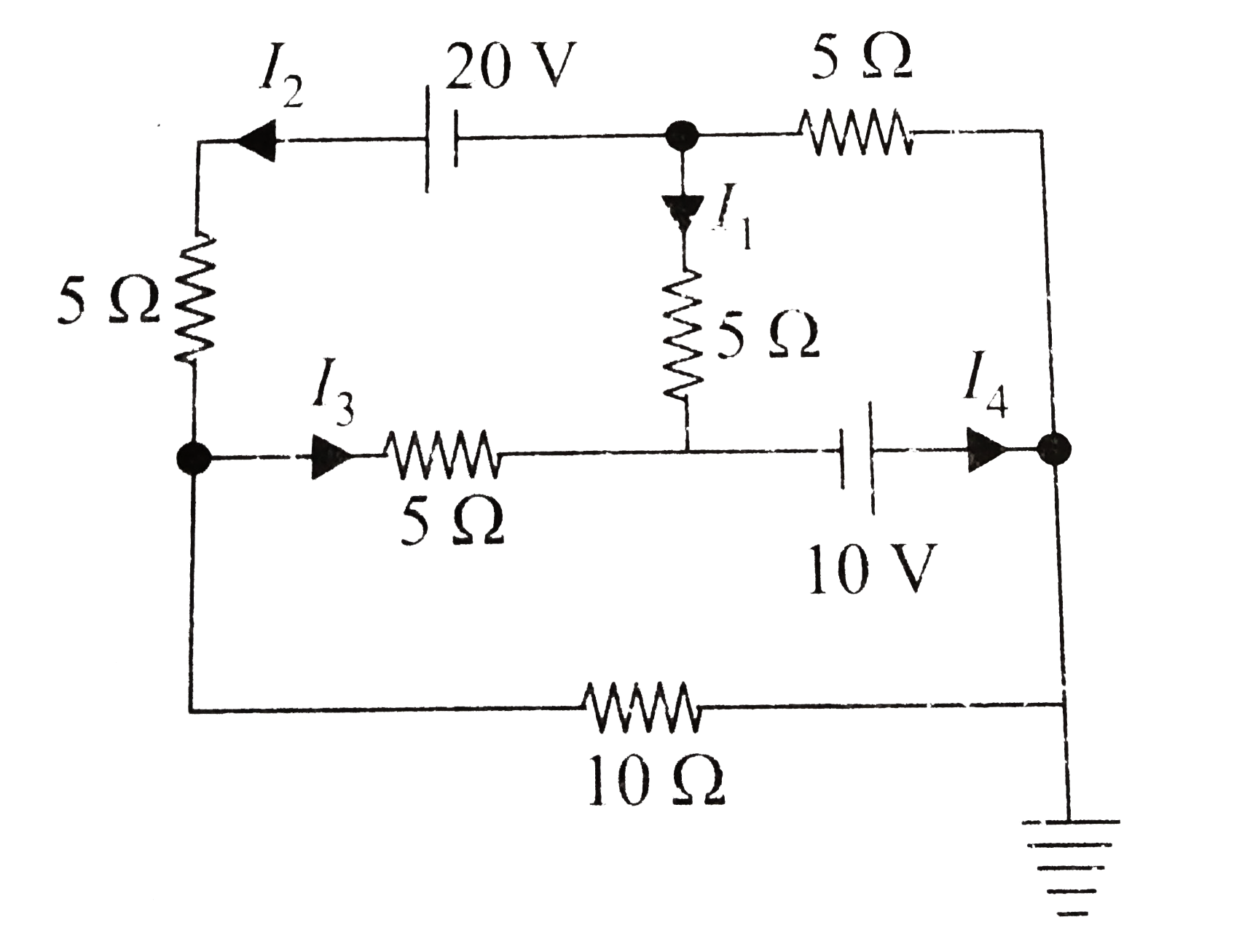
The value of current I4 is
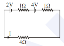
View SolutionFor the circuit shown in the figure current I will be
View SolutionThe current I shown in the circuit is
View SolutionIn the circuit shown in figure
For what ratio R2R4, current through R3 will be zero
View Solution
