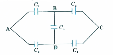
A potential of V=3000V is applied to a combination of four initially uncharged capacitors as shown in the figure. Capacitors A, B, C and D have capacitances CA=6.0μF,CB=5.2μF,CC=1.5μFandCD=3.8μF, respectiely. If the battery is disconnected, then potential difference across capacitor B is (approximately)

3000 V
zero
530 V
350 V
The correct Answer is:D
Topper's Solved these Questions
- ELECTROSTATIC POTENTIAL AND CAPACITORSBOOK - DC PANDEYCHAPTER - ELECTROSTATIC POTENTIAL AND CAPACITORSEXERCISE - (B) Chapter exercises
20 Videos
- ELECTROSTATIC POTENTIAL AND CAPACITORSBOOK - DC PANDEYCHAPTER - ELECTROSTATIC POTENTIAL AND CAPACITORSEXERCISE - (C) Chapter exercises
50 Videos
- ELECTROSTATIC POTENTIAL AND CAPACITORSBOOK - DC PANDEYCHAPTER - ELECTROSTATIC POTENTIAL AND CAPACITORSEXERCISE - Check point 2.5
20 Videos
- ELECTROMAGNETIC WAVESBOOK - DC PANDEYCHAPTER - ELECTROMAGNETIC WAVESEXERCISE - Sec C
22 Videos
- ELECTROSTATICSBOOK - DC PANDEYCHAPTER - ELECTROSTATICSEXERCISE - Medical entrances gallery
37 Videos
Similar Questions
Knowledge Check
Four capacitors with capacitances C1=1μF,C2=1.5μF,C3=2.5μF and C4=0.5μF are connected as shown in Fig, to a 30 voltg source. The potentail difference between points a and b is
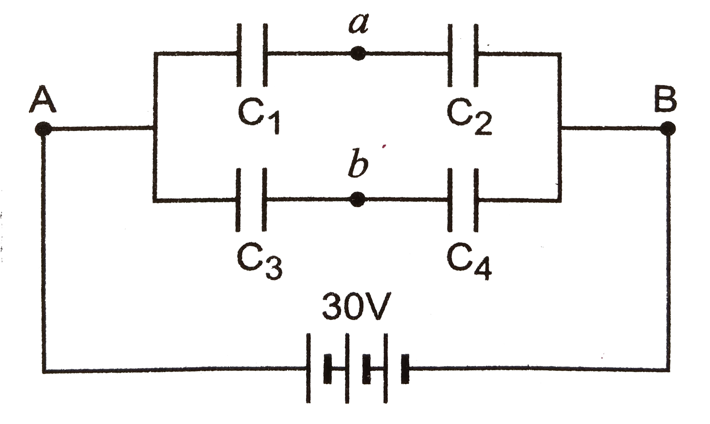 A5VB9VC10VD13V
A potential difference of 300 volts is applied to a combination of 2.0μF and 8.0μF capacitors connected in series. The charge on the 2.0μF capacitor is
A2.4×10−4CB4.8×10−4CC7.2×10−4CD9.6×10−4CThree capacitors of capacitance 1μF,2μF and 3μF are connected in series and a potential difference of 11V is applied across the combination. Then, the potential difference across the plates of 1μF capacitor is
A2VB4VC1VD6V
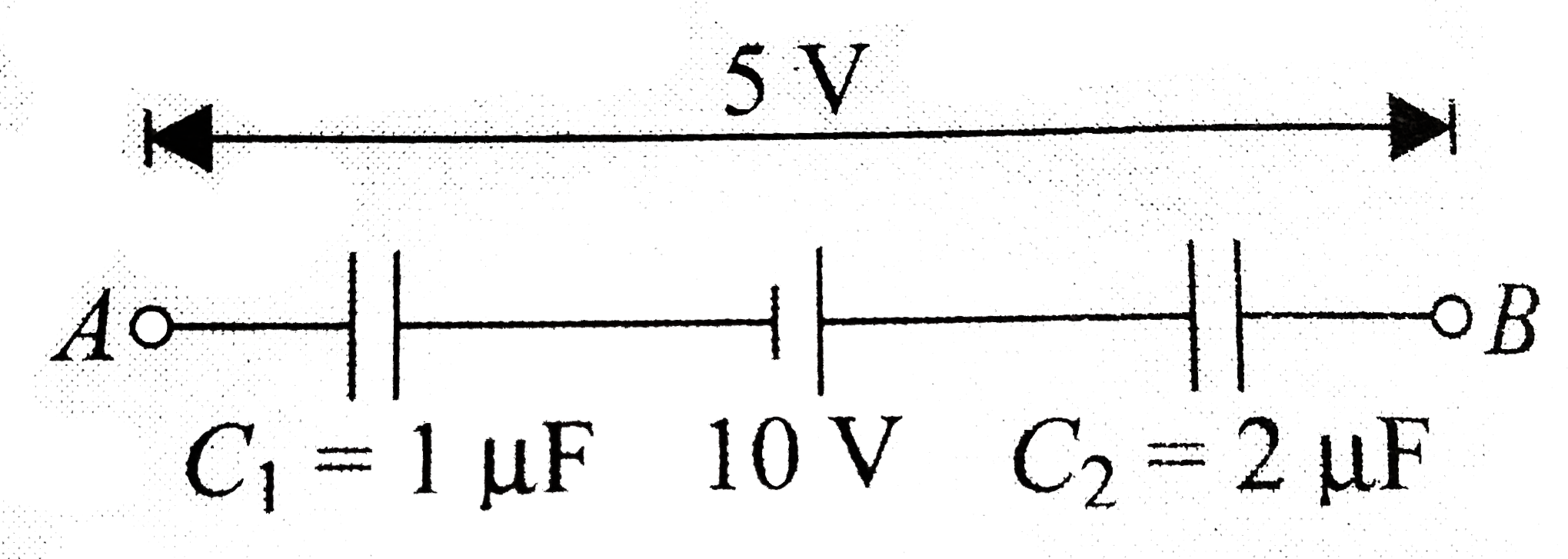
A circuit has section AB as shown in The emf of the cell is 10V, and the capacitors have capacitances C1=1μF and C2=2μF.
 .
.
View Solution
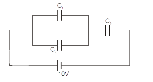
(i) Find the equivalent capacitance of the combination shown in the figure (a), when C1=2.0μF,C2=4.0μFandC3=3.0μF
(ii) The input terminals A and B in Fig. (a) are connected to a battery of 12 V. Find the potential and the charge of each capacitor.
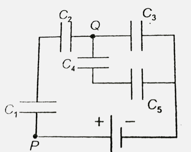
View SolutionIn the circuit shown C1=15μF,C2==30μF,C3=30μF,C4=30μF and C5=60μF. At steady state, the potential difference between points P and Q is 50 V. Calculate the potential difference across capacitor with capacitance C5
View SolutionTwo capacitors of capacitances C1=2μF and C2=8μF are connected in series and the resulting combination is connected across a 300V battery. Calculate the charge, potential difference and energy stored in the capacitor separately.
View SolutionTwo capacitors of capacitances C1=2μF and C2=8μF are connected in series and the resulting combination is connected across a 300V battery. Calculate the charge, potential difference and energy stored in the capacitor separately.
View Solution

