In the circuit shown in Fig.4.20 both the ammeter and the cell have negligible resistance. Three external resistors are identical. When the switch S is opened, the ammeter reads 0.6 A. What will the ammeter read when the switch S is closed ?
Step by step video & image solution for In the circuit shown in Fig.4.20 both the ammeter and the cell have negligible resistance. Three external resistors are identical. When the switch S is opened, the ammeter reads 0.6 A. What will the ammeter read when the switch S is closed ? by Physics experts to help you in doubts & scoring excellent marks in Class 12 exams.
Topper's Solved these Questions
- BOOK - SL ARORACHAPTER - CURRENT ELECTRICITYEXERCISE - Problems From Competitive18videos
CURRENT ELECTRICITY
- BOOK - SL ARORACHAPTER - CURRENT ELECTRICITYEXERCISE - Problems For Self101videos
CURRENT ELECTRICITY
- BOOK - SL ARORACHAPTER - CHEMICAL EFFECT OF CURRENTEXERCISE - TYPE-B5videos
CHEMICAL EFFECT OF CURRENT
- BOOK - SL ARORACHAPTER - ELECTRIC POTENTIAL AND ELECTRIC FLUXEXERCISE - Problems for self practive61videos
ELECTRIC POTENTIAL AND ELECTRIC FLUX
Similar Questions
(a) Explain with the help of a labelled circuit diagram, how you will find the resistance of a combination of three resistors of resistances R1,R2 and R3 joined in parallel.
(b) In the diagram shown below, the cell and the ammeter both have negligible resistance. The resistors are identical.
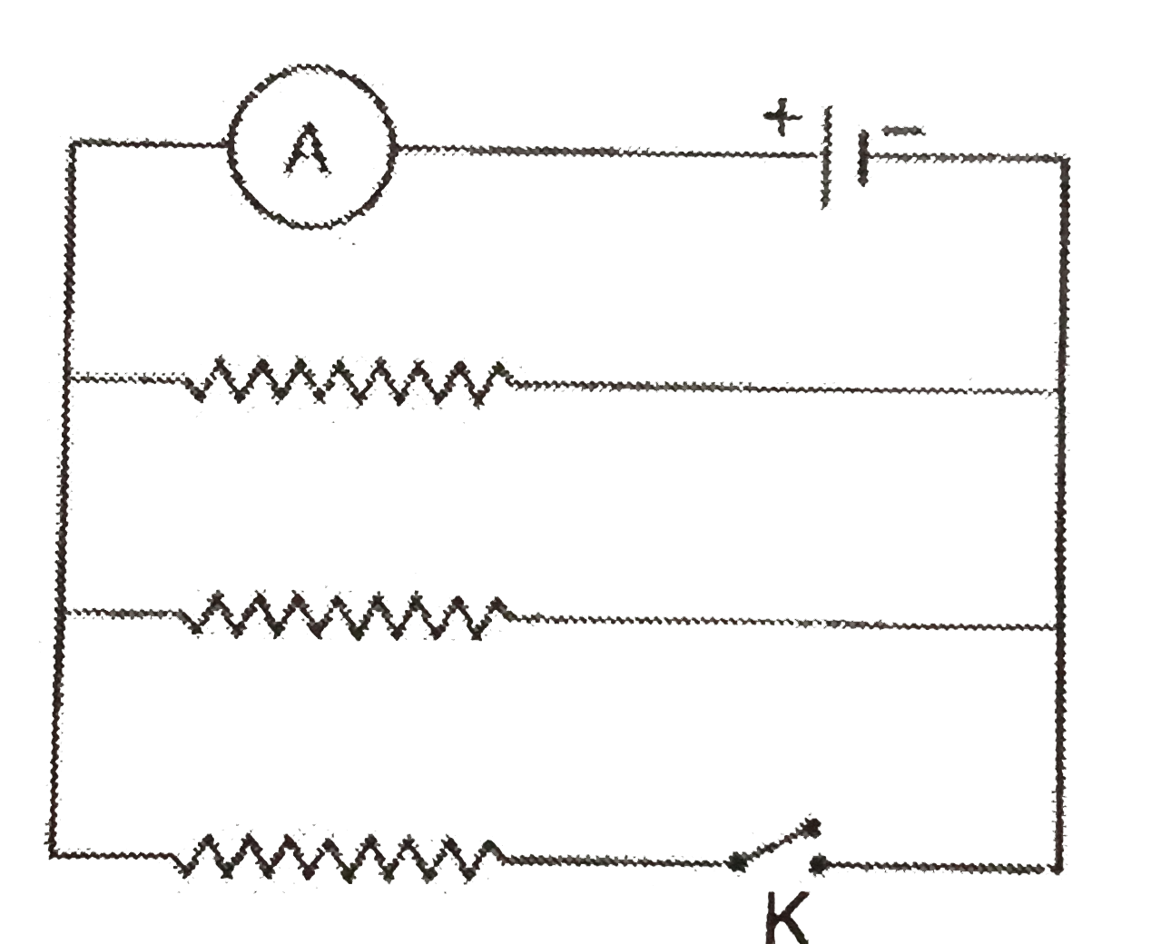
With the switch K open, the ammeter reads 0.6A. What will be the ammeter reading when the switch is closed?View SolutionIn the given circuit diagram, the cell and the ammeter, both have negligible resistance. The resistances are identical. With the switch K open, the ammeter reads 0.6 A. What will be the ammeter reading when the switch is closed?
 View Solution
Knowledge Check
- Question 1 - Select One
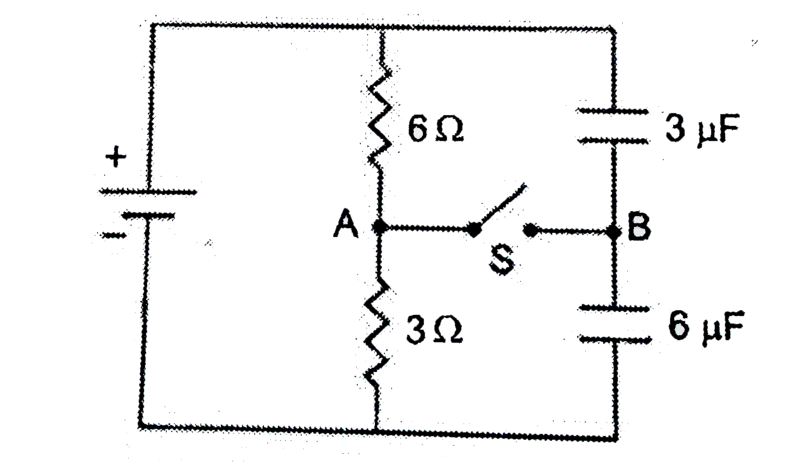
In the circuit shown above, when then switch S is closed,Ano charge flows through SBcharge flows from A to BCcharge flows from B to ADcharge flows initially from A to B and later from B to A - Question 2 - Select One
In the given circuit , the three lamps are identical When switch S is closed then
 ALamp P becomes dimmerBLamp P is as bright as lamp QCLamp Q is not as bright as lamp RDLamp P remains as bright as before .
 - Question 3 - Select One
In the circuit shown in Fig. 6.50, an idel ammeter and an ideal voltmeter are used. Whan the key is open, the voltmeter reads 1.53V. When the key is closed, the ammeter reads 1.0A and the voltmeter reads 1.03V. The resistance R is
 A0.5ΩB1.03ΩC1.53ΩD1.53Ω
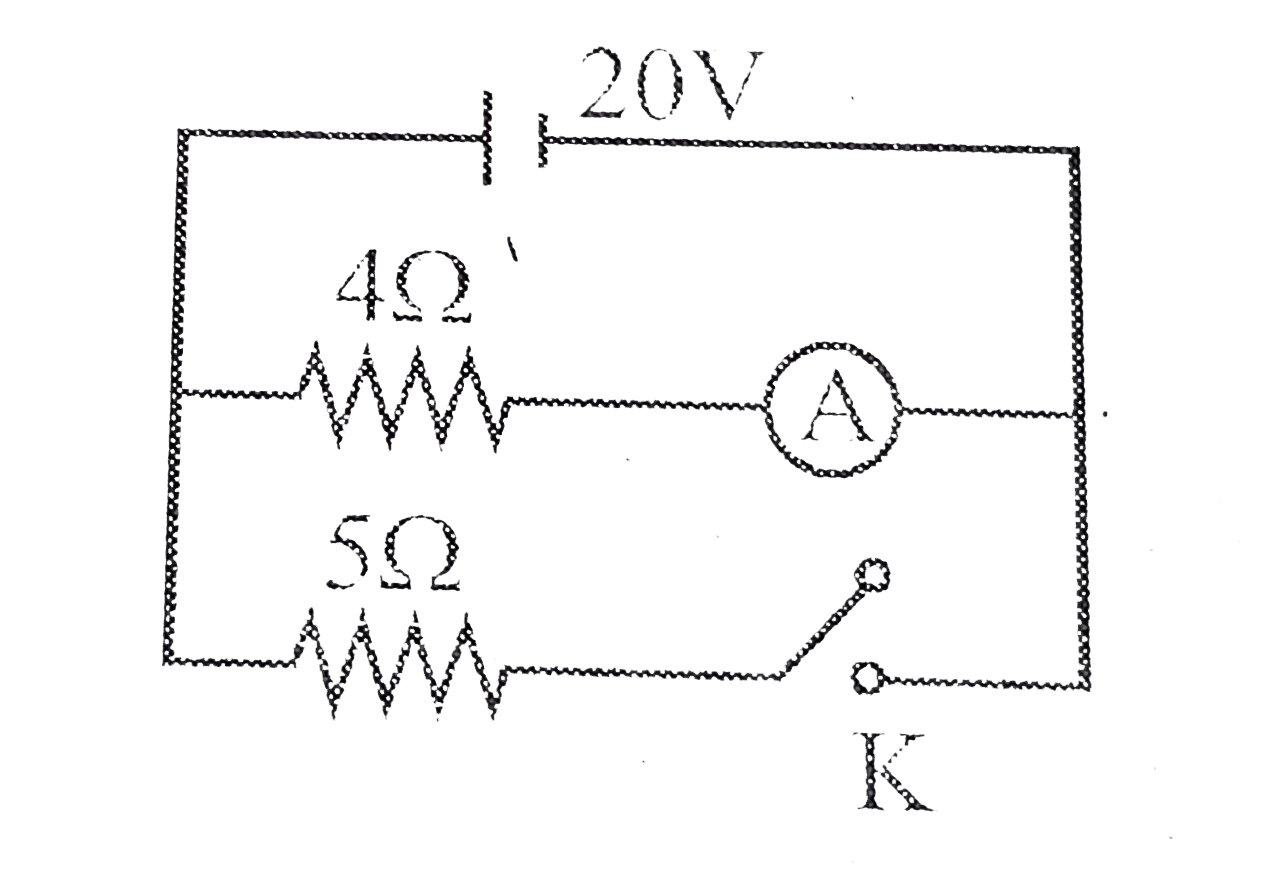
In the given figure when the key is open the ammeter reading is 5 amp. What will be the ammeter reading when the key is closed
 View Solution
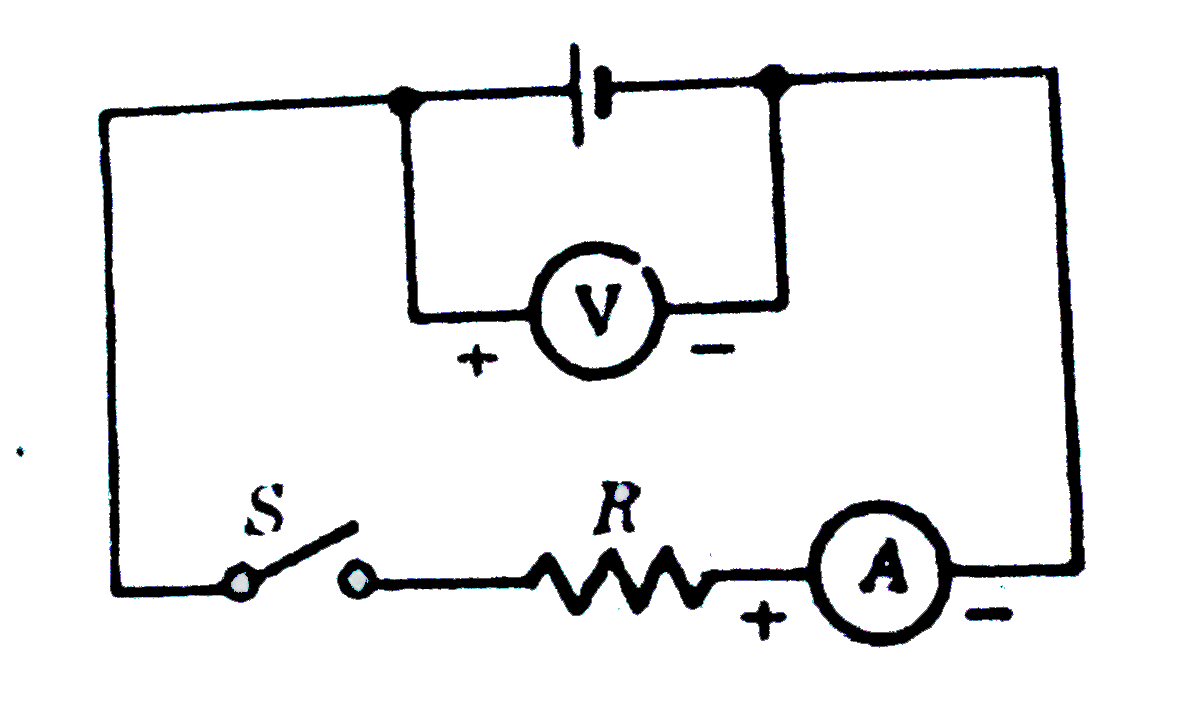
In the circuit shown in Fig. 4.67, the resistance of the ammeter A is negligible and that of thevoltmeter V is very high. When the switch S is open, the reading of voltmeter is 1.53 V. On closing the switch S, the reading of ammeter drops to 1.03 V. Calculate : (i) emf of the cell (ii) internal resistance of the cell (iii) value of R.
 View Solution
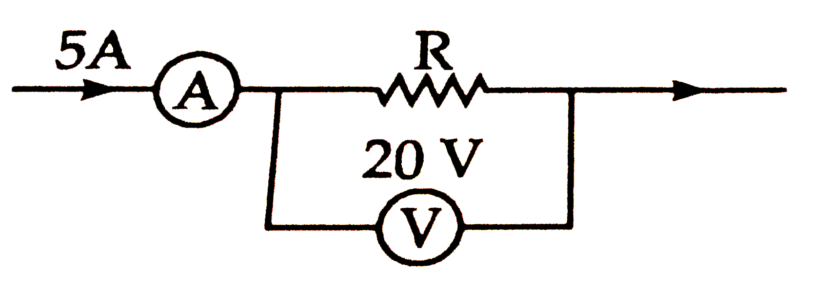
In the adjacent circuit the ammeter reads 5.0 A and voltmeter reads 20V. The value of resistance R is
 View Solution
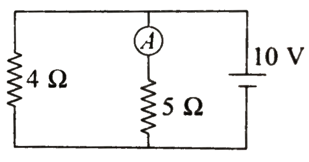
In the circuit shows in Fig. 6.41, the reading of the ammeter is (assume internal resistance of the battery be to zero)
 View Solution
In the circuit shown below, the ammeter A reads 5 A and the voltmeter V reads 20 V The correct value of resistance R is
 View Solution

