(a) Explain with the help of a labelled circuit diagram, how you will find the resistance of a combination of three resistors of resistances R1,R2 and R3 joined in parallel.
(b) In the diagram shown below, the cell and the ammeter both have negligible resistance. The resistors are identical.
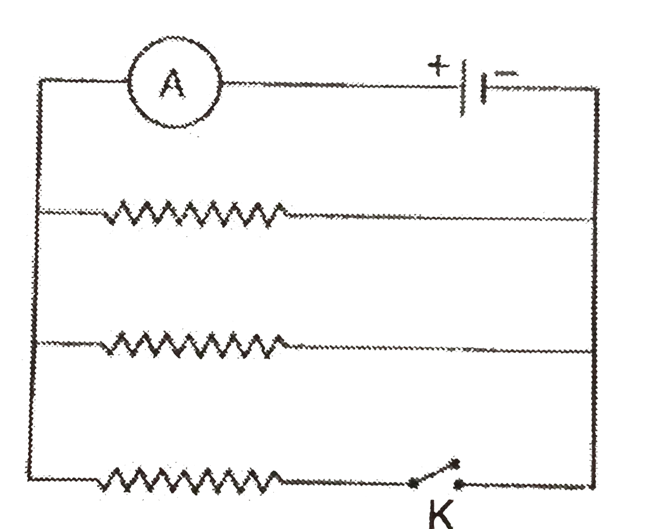
With the switch K open, the ammeter reads 0.6A. What will be the ammeter reading when the switch is closed?
The correct Answer is:(b) 0.9A
Step by step video, text & image solution for (a) Explain with the help of a labelled circuit diagram, how you will find the resistance of a combination of three resistors of resistances R_(1),R_(2) and R_(3) joined in parallel. (b) In the diagram shown below, the cell and the ammeter both have negligible resistance. The resistors are identical. With the switch K open, the ammeter reads 0.6A. What will be the ammeter reading when the switch is closed? by Physics experts to help you in doubts & scoring excellent marks in Class 10 exams.
Updated on:21/07/2023Topper's Solved these Questions
- ELECTRICITY BOOK - LAKHMIR SINGH & MANJIT KAURCHAPTER - ELECTRICITY EXERCISE - Very Short Answer Type Questions
1 Videos
- ELECTRICITY BOOK - LAKHMIR SINGH & MANJIT KAURCHAPTER - ELECTRICITY EXERCISE - Short Answer Type Questions
2 Videos
- ELECTRICITY BOOK - LAKHMIR SINGH & MANJIT KAURCHAPTER - ELECTRICITY EXERCISE - Sample Problem
1 Videos
- MAGNETIC EFFECT OF ELECTRIC CURRENT BOOK - LAKHMIR SINGH & MANJIT KAURCHAPTER - MAGNETIC EFFECT OF ELECTRIC CURRENT EXERCISE - NCERT BOOK
2 Videos
Similar Questions
In the given circuit diagram, the cell and the ammeter, both have negligible resistance. The resistances are identical. With the switch K open, the ammeter reads 0.6 A. What will be the ammeter reading when the switch is closed?
View SolutionIn the circuit shown in Fig.4.20 both the ammeter and the cell have negligible resistance. Three external resistors are identical. When the switch S is opened, the ammeter reads 0.6 A. What will the ammeter read when the switch S is closed ?
View Solution
Knowledge Check
The resistance of ammeter is R0
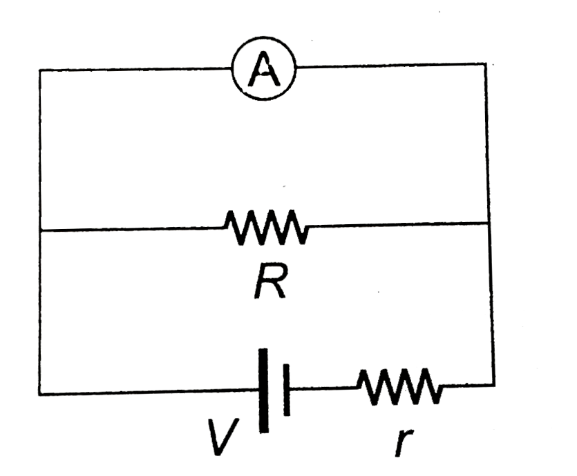 AIf r=0, if the value of resistance R increase, the current in ammeter will remain sameBIf r=0, if the value of resistance R decrease, the current in ammeter will remain sameCIf r≠0, if R increase, the current in ammeter will remian sameDIf r≠0, if R increases, the current in ammeter will increase
In the circuit shown below, the ammeter reading is zero. Then, the value of the resistance R is
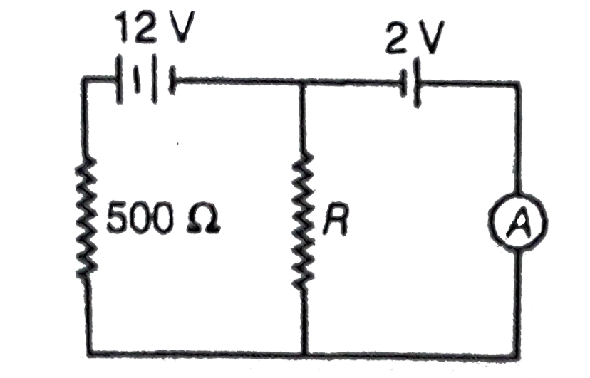 A50ΩB100ΩC200ΩD400Ω
In the circuit shown below, the ammeter reading is zero. Then, the value of the resistance R is
 A50ΩB100ΩC200ΩD400Ω
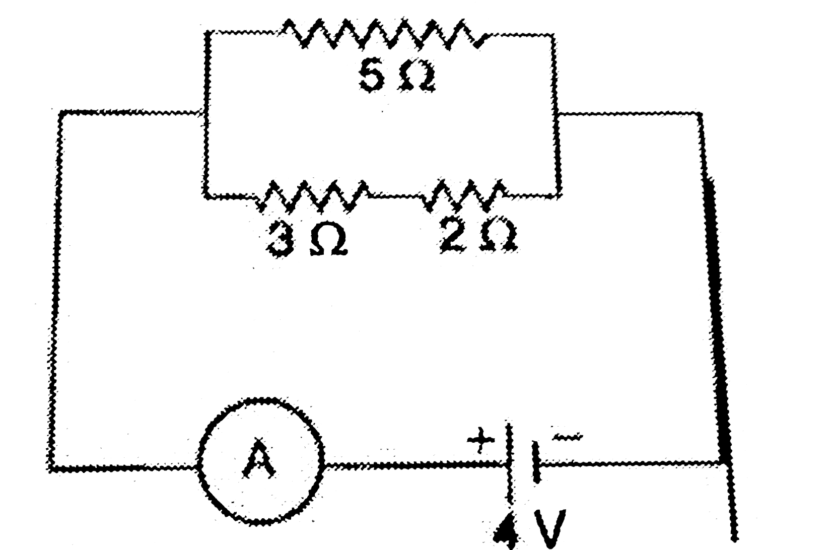
(a) With the help of a circuit diagram, obtain the relation for the equivalent resistance of two resistances connected in parallel.
(b) In the circuit diagram shown below, find:
(i) Total resistance.
(ii) Current shown by the ammeter A
View SolutionEstablish a relationship to determine the equivalent resistance R of a combination of three resistors having resistances R1,R2andR3 connected in series.
(b) Calculate the equivalent resistance R of a combination of three resistors of 2Ω,3Ωand6Ω joined in parallel.
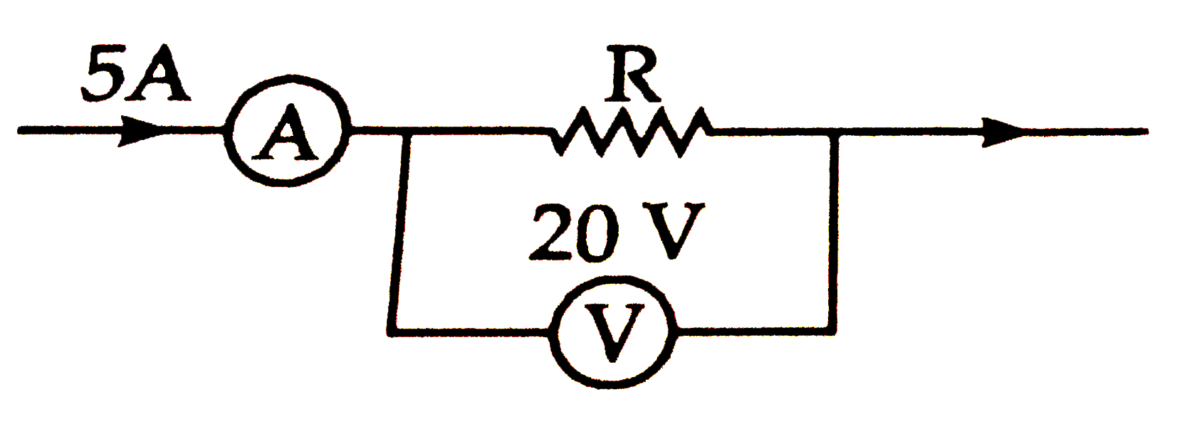
View SolutionIn the adjacent circuit the ammeter reads 5.0 A and voltmeter reads 20V. The value of resistance R is
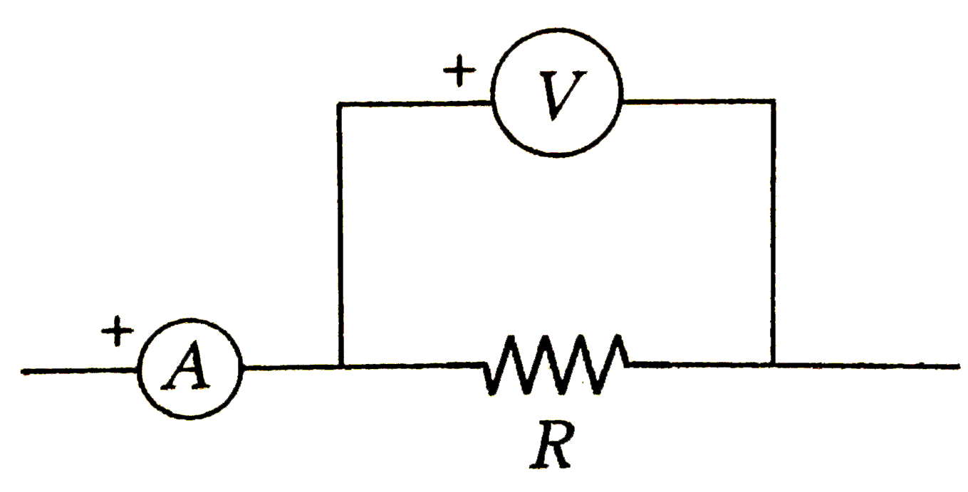
View SolutionAn ammeter A, a voltmeter V and a resistance R are connected as shown in the figure. If the voltmeter reading is 1.6V and the ammeter reading is 0.4A, then R is
View SolutionIn the circuit shown below, the ammeter A reads 5 A and the voltmeter V reads 20 V The correct value of resistance R is

View Solution
