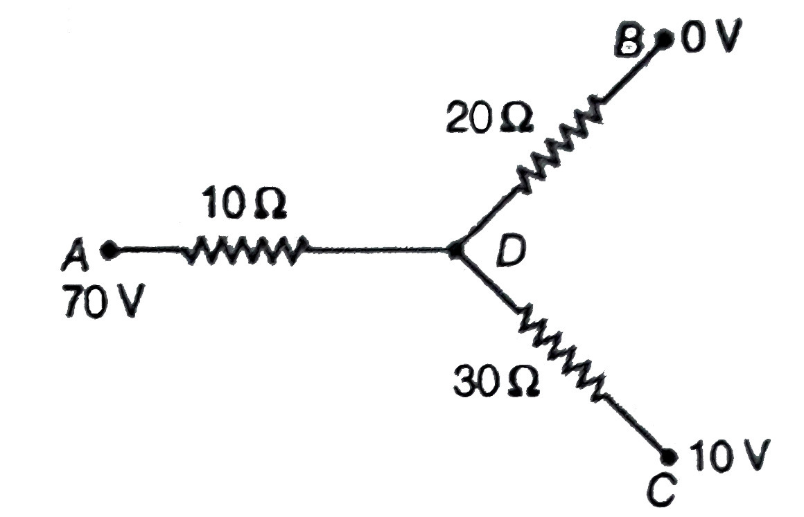
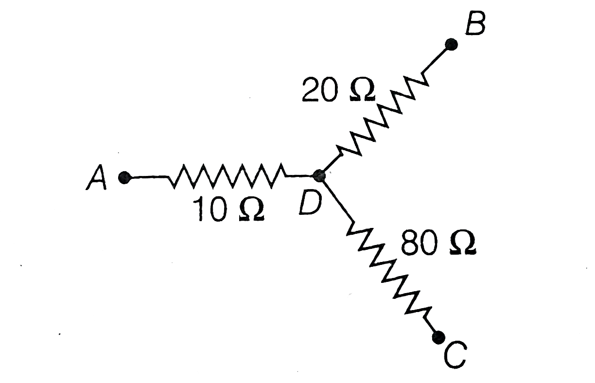
For the network shown in figure, points A, B and C are at potentials of 70 V, zero and 10 V respectively
A
point D is at a potential of 40 V
B
the currents in the sections AD, DB and DC are in the ratio 4:3:2
C
the current in the sections AD, DB and DC are in the ratio 1:2:3
D
the network draws a total power of 100 W
Video Solution
Text Solution
The correct Answer is:A
Consider the current distributions in the circuit as shown below
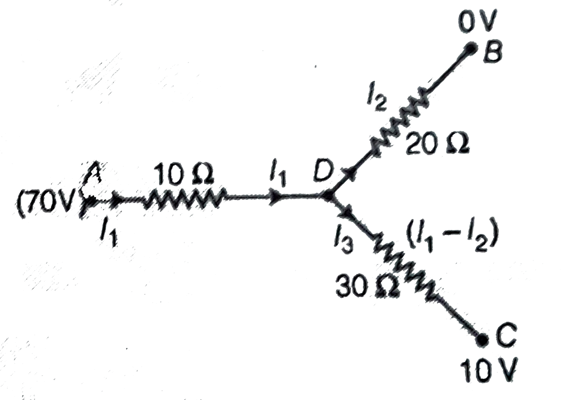
By KVL,VA−l110−l220−VB=0
⇒l110+l220=70
VA−l110−l330−VC=0
⇒ l110+l330=60
Also, l3=l1−l2
So, Eq. (ii) becomes
l110+30(l1−l2)=60
l140−30l2=60
Solving Eqs. (i) and (iii), we get
l2=2A,l1=3A,l3=1A
Potential drop across branch AD,
VA−VD=l1×10⇒70−VD=30⇒VD=40V
|
Updated on:21/07/2023
Related Playlists
- BOOK - BITSAT GUIDECHAPTER - CURRENT ELECTRICITYEXERCISE - Bitsat Archives26videos
CURRENT ELECTRICITY
- BOOK - BITSAT GUIDECHAPTER - CATHODE RAY, PHOTOELECTRIC EFFECT AND X-RAYSEXERCISE - BITSAT Archives6videos
CATHODE RAY, PHOTOELECTRIC EFFECT AND X-RAYS
- BOOK - BITSAT GUIDECHAPTER - ELECTRIC CAPACITOREXERCISE - BITSAT archives6videos
ELECTRIC CAPACITOR
Knowledge Check
- Question 1 - Select One or More
In the network shown in fig. , points A, B, and C are at potentials of 70 V, 0, and 10V, respectively.
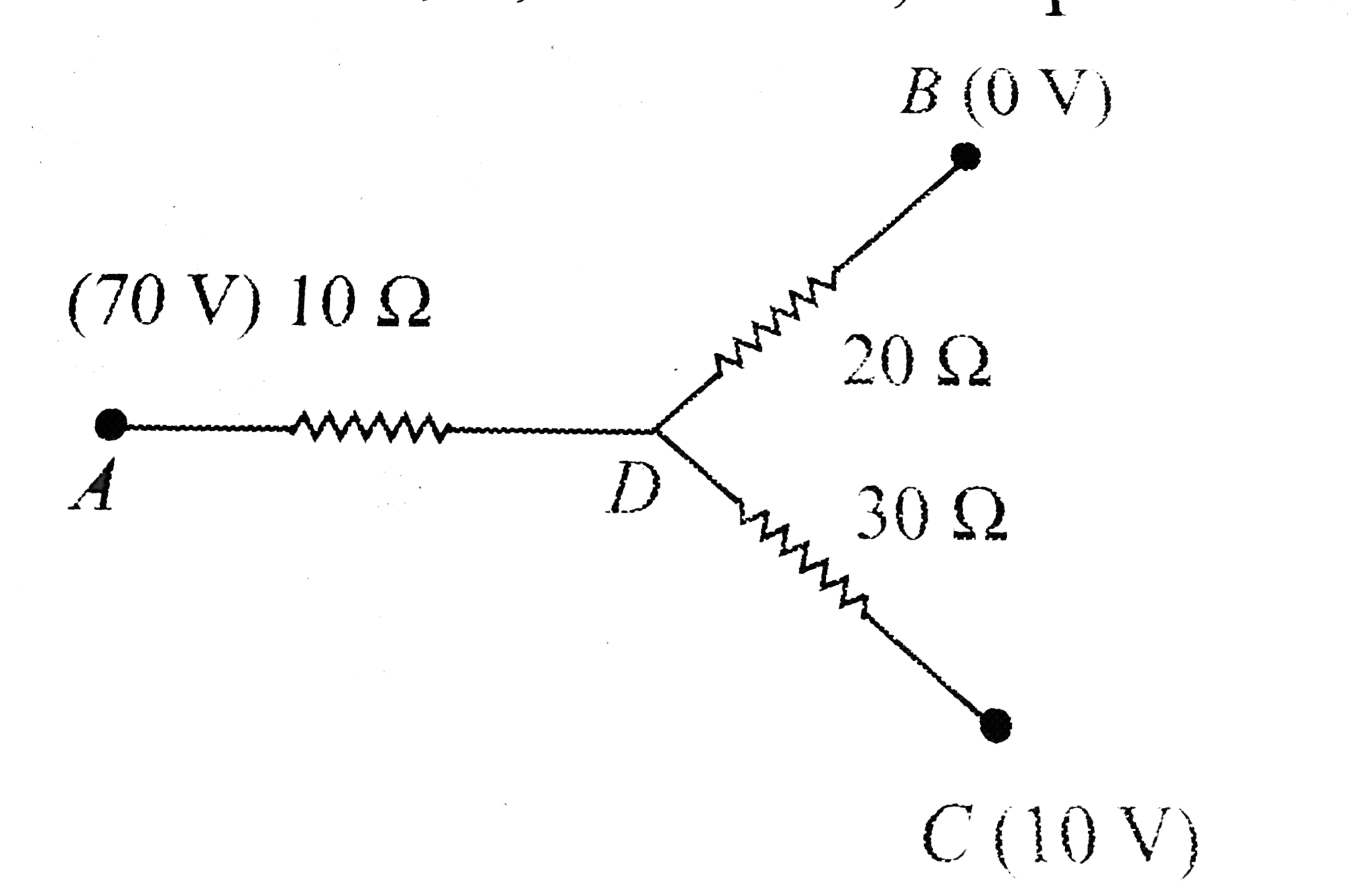 APoint D is at a potential of 40 V.BThe currents in the sections AD, DB, DC are in the ratio 3 : 2 : 1CThe currents in the section AD, DB, DC are in the ratio 1 : 2 : 3.DThe network draws a total power of 200 W.
 - Question 1 - Select One
A hollow conducting sphere is placed in an electric field produced by a point charge placed at P as shown in figure.
Let VA,VB,VC be the potentials at points A,BandC respectively. Then
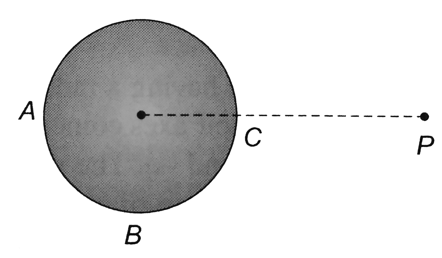 AVC>VBBVB>VCCVA>VBDVA=VC
 - Question 1 - Select One
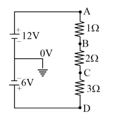
In the circuit diagram shown in figure, the potentials of the points B, C and D are respectively.
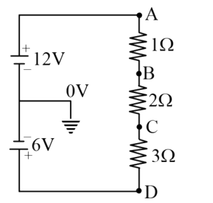 A12V,10V,6VB11V,9V,6VC11V,9V,0VD12V,10V,0V
 - Question 1 - Select One
Three uncharged capacitors of capacities C1,C2 and C3 are connected as shown in the figure to one another and the potentials V1,V2 and V3 respectively. Then the potential at O will be
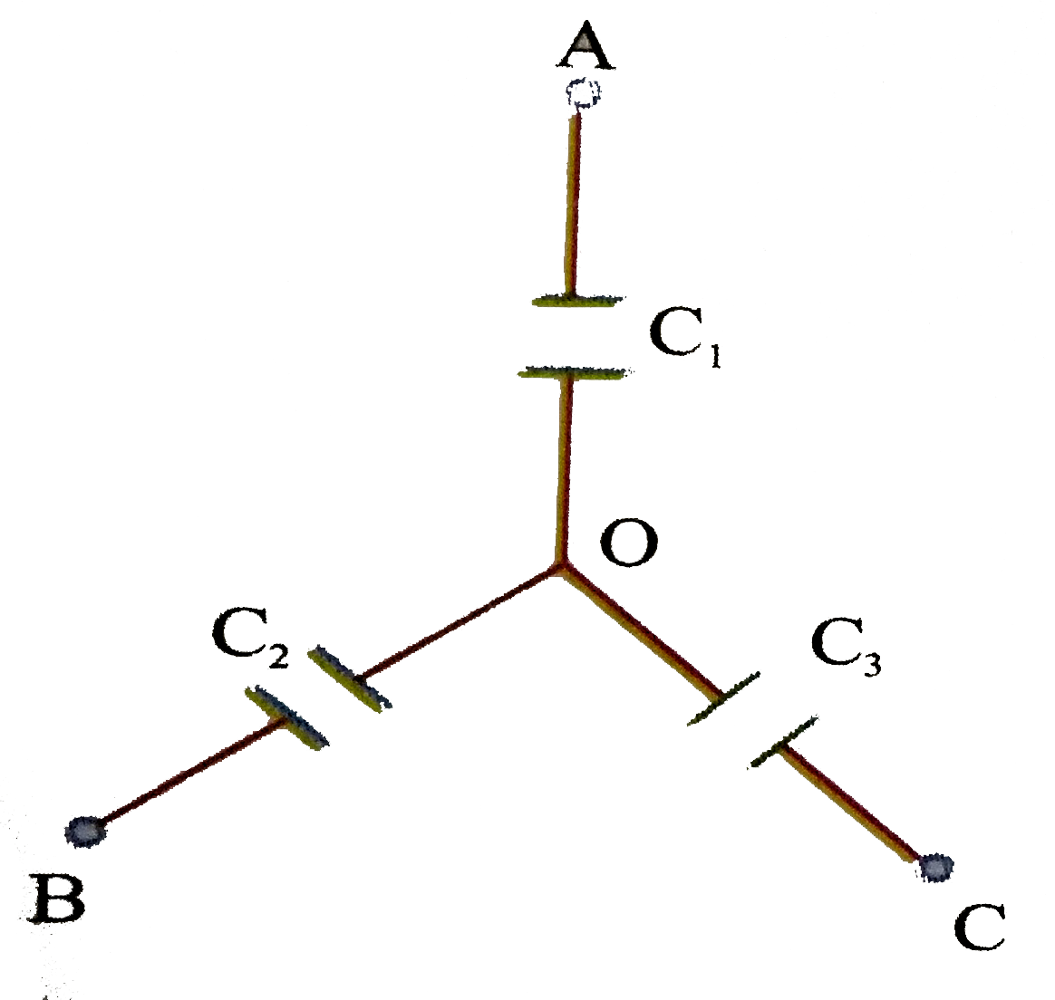 .AV1C1+V2C2+V3C3C1+C2+C3BV1+V2+V3C1+C2+C3CV1(V2+V3)C1(C2+C3)DV1V2V3C1C2C3
 - Question 1 - Select One
Three resistance are joined together to form a letter Y, as shown in figure. If the potentials of the terminals A,B and C are 6V,3V and 2V respectively, then the potential of the point O will be
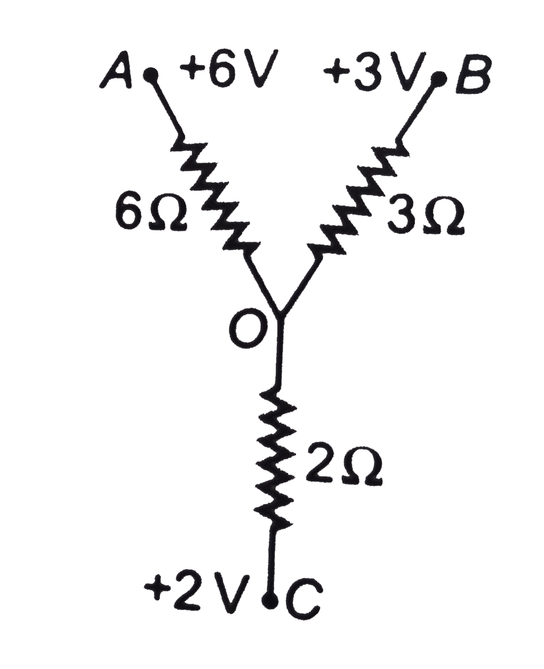 A4VB3VC2.5VD0V
 - Question 1 - Select One
A current of 2 A flows in an electric circuit as shown in figure. The potential difference (VR−VS), in volts (VR and VS are potentials at R and S respectively is
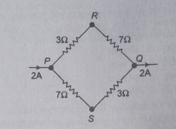 A-4B(+2)C(+4)D-2
Similar Questions
In the circuit given here, the points A,B and C are 70 V, zero, 10 V respectively . Then,
 View Solution
In the circuit diagram shown in Figure , the potentials of the points B, C and D are respectively -
 View Solution
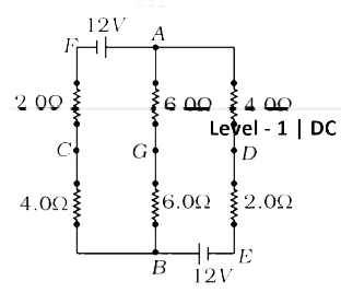
In the network shown in the figure, the potential difference between A and B is :
 View Solution
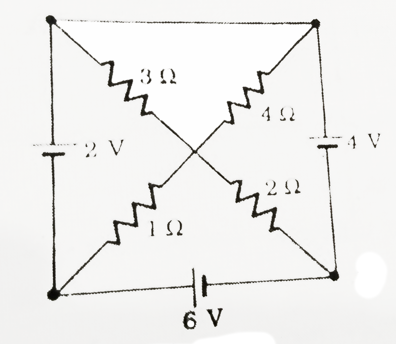
In the network shown in figure. (i) calculate the current of the 6V battery and (ii) determine the potential difference between the points A and B.View Solution

