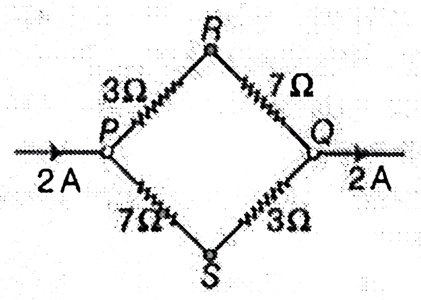
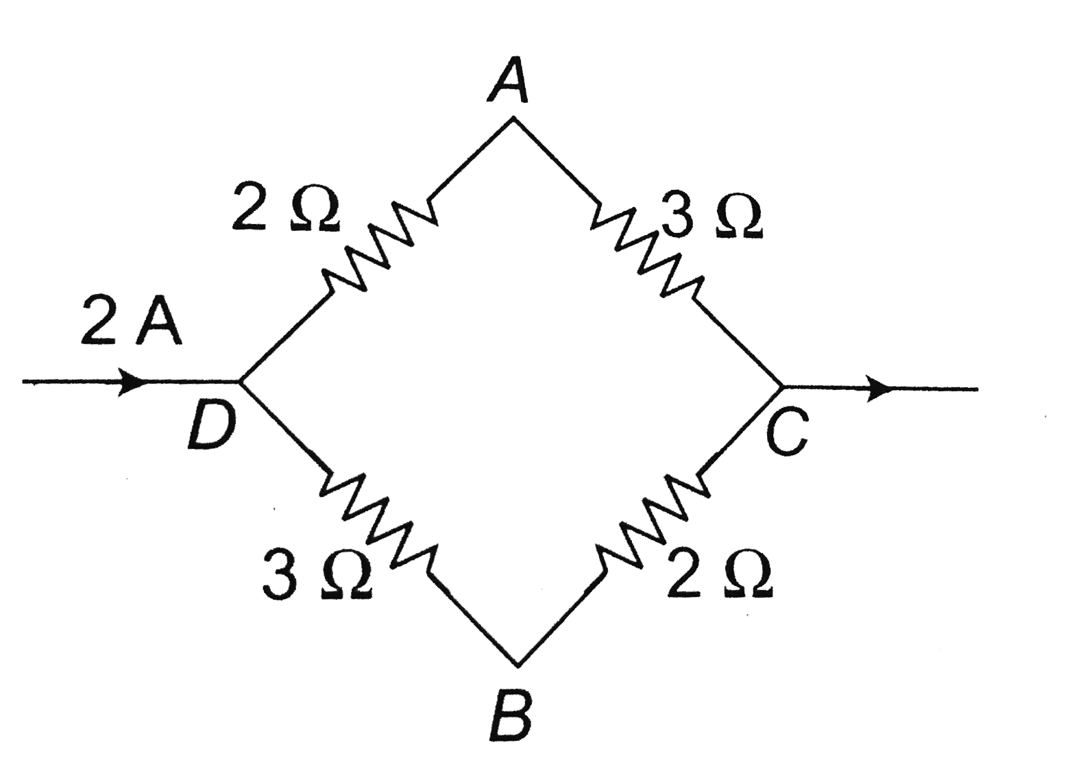
A current of 2 A flows in an electric circuit as shown in figure. The potential difference (VR−VS), in volts (VE and VS are potenitals at R and S respectively) is
A
−4
B
+2
C
+4
D
−2
Video Solution
Text Solution
The correct Answer is:C
Current through each arm
PQR and PSQ = 1A
Vp−VR=3V
VP−VS=7V
From Eqs. (i) and (ii), we get
VR−VS=+4V
|
Topper's Solved these Questions
- CURRENT ELECTRICITYBOOK - BITSAT GUIDECHAPTER - CURRENT ELECTRICITYEXERCISE - Bitsat Archives
26 Videos
- CATHODE RAY, PHOTOELECTRIC EFFECT AND X-RAYSBOOK - BITSAT GUIDECHAPTER - CATHODE RAY, PHOTOELECTRIC EFFECT AND X-RAYSEXERCISE - BITSAT Archives
6 Videos
- ELECTRIC CAPACITORBOOK - BITSAT GUIDECHAPTER - ELECTRIC CAPACITOREXERCISE - BITSAT archives
6 Videos
Similar Questions
Knowledge Check
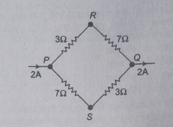
A current of 2 A flows in an electric circuit as shown in figure. The potential difference (VR−VS), in volts (VR and VS are potentials at R and S respectively is
 A-4B(+2)C(+4)D-2
A current of 2 A flows in an electric circuit as shown in figure. The potential difference (VR−VS), in volts (VR and VS are potentials at R and S respectively is
 A-4B(+2)C(+4)D-2
A current of 2A flows in a system of conductor as shown. The potential difference (VA−VB)
 A+2VB+1VC−1VD−2V
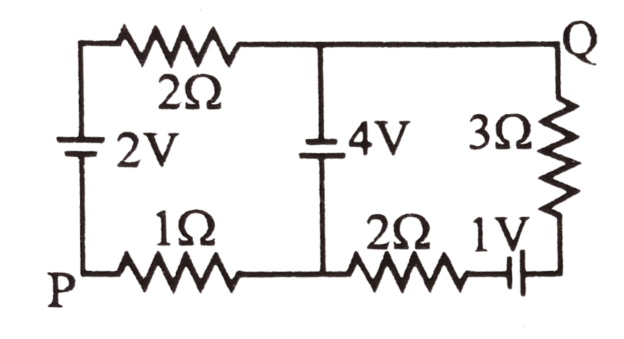
In the circuit shown, what is the potential difference VPQ?
View SolutionIn the part of a circuit shown in figure, the potential different
(VG−VH) between points G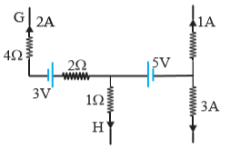
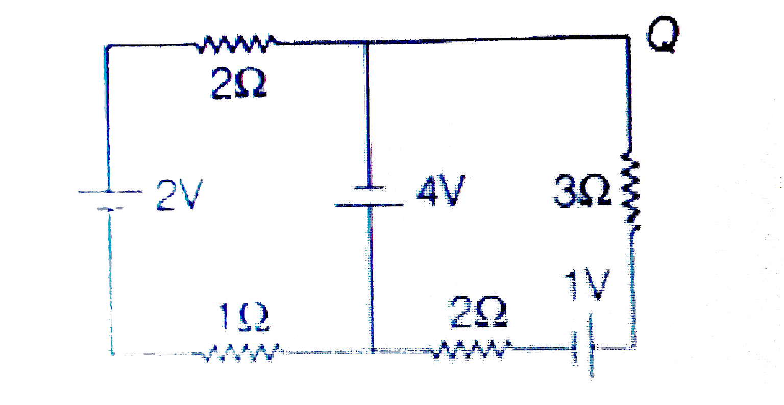
View SolutionIn the circuit shown, what is the potential different VPQ ?
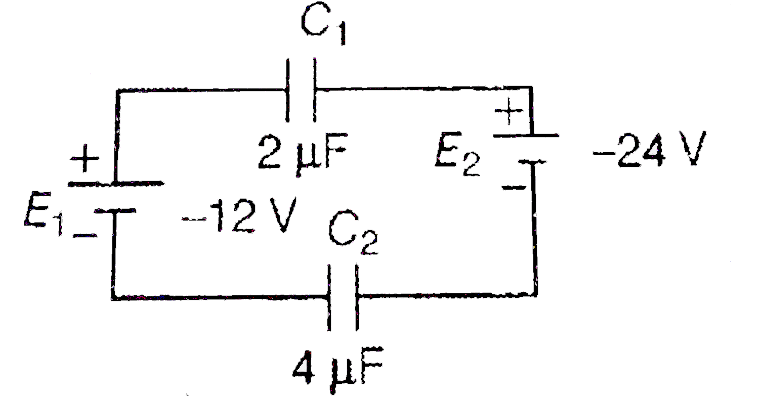
View SolutionTwo capacitors C1 and C2 are connected in a circuit as shown in figure. The potential difference (VA−VB) is
View SolutionIn the part of a circuit branch shown in figure-5.304 the potential difference Vab at t=1s is:

View Solution

