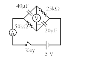
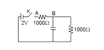
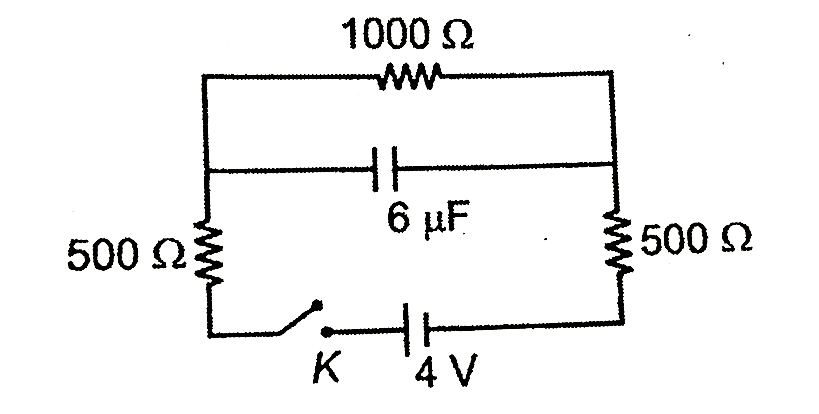
In the circuit shown below , key is pressed at time t=0, choose the correct statement.
A
At time t=0, current flow through the battery is 4mA
B
At time t→∞, current flow through the battery is 4mA
C
At time t→∞, charge on capacitor is 1.2μC
D
At time t→∞, charge on capacitor is 6μC
Video Solution
Text Solution
The correct Answer is:A
At steady state capacitor acts as open circuit
At t=0, capacitor is shorted , hence
i=4500+500=4mA
As time t→∞, capacitor is fully charge and offer infinite resistance
hence i=41000+500+500=2mA
Voltage across capacitor at steady state
Vc=10002000×4=2V
Charge on capacitor = Q = CV
Q6μF×2V=12μC
|
Topper's Solved these Questions
Similar Questions
Knowledge Check
Choose the incorrect statement for keys:-
AA pair of contrasting characters is called coupletBThey are analytical in natureCFamily, genus and species can be identified with a single keyDEach statement in the key is called leadIn the circuit shown below, the key is pressed at time t = 0 . Which of the following statements (s) is (are) true?
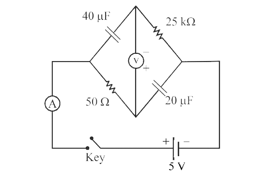 AThe voltmeter displays (−5V)ass∞nasthekeyispressed,anddisplays(+5 V) after a long timeBThe volmeter will display 0V at time t = In 2 seconds.CThe current in the ammeter becomes 1//e of the initial value after 1 secondDThe current in the ammeter becomes zero after a long time.
In the circuit shown in the figure, switch S is closed at time t=0. Select the correct statements.
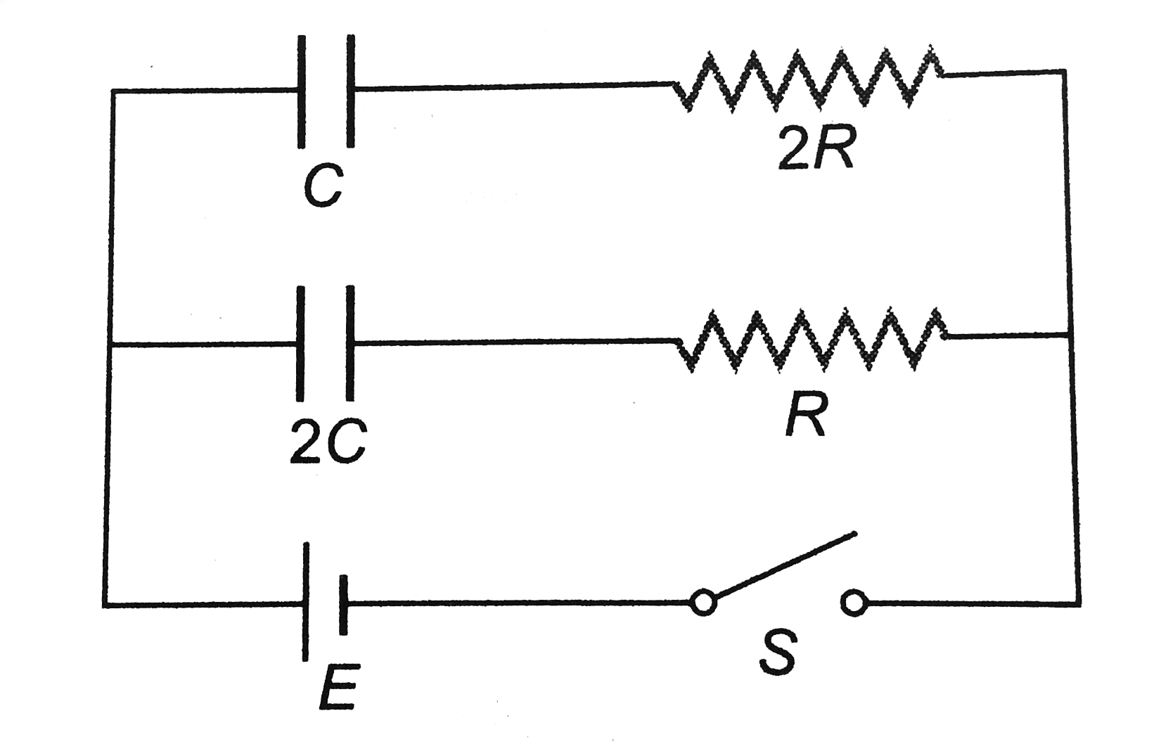 ARate of increase of charge is same in both the capacitorsBRatio of charge stored in capacitors C and 2C at any time t would be 1:2CTime constants of both the capacitors are equalDSteady state chares on capacitors C and 2C are in the ratio of 1:2
In the given circuit, the switch S is closed at time t=0 then select the correct statement for current l in resistance PQ as shown in the figure
_PHY_E05_091_Q01.png)
View SolutionIn the given circuit, the switch S is closed at time t = 0, then select the correct statement for current l in resistance PQ as shown in the figure.
_PHY_E05_045_Q01.png)
View SolutionIn the circuit shown below, the key K is closed at t = 0. The current through the battery is
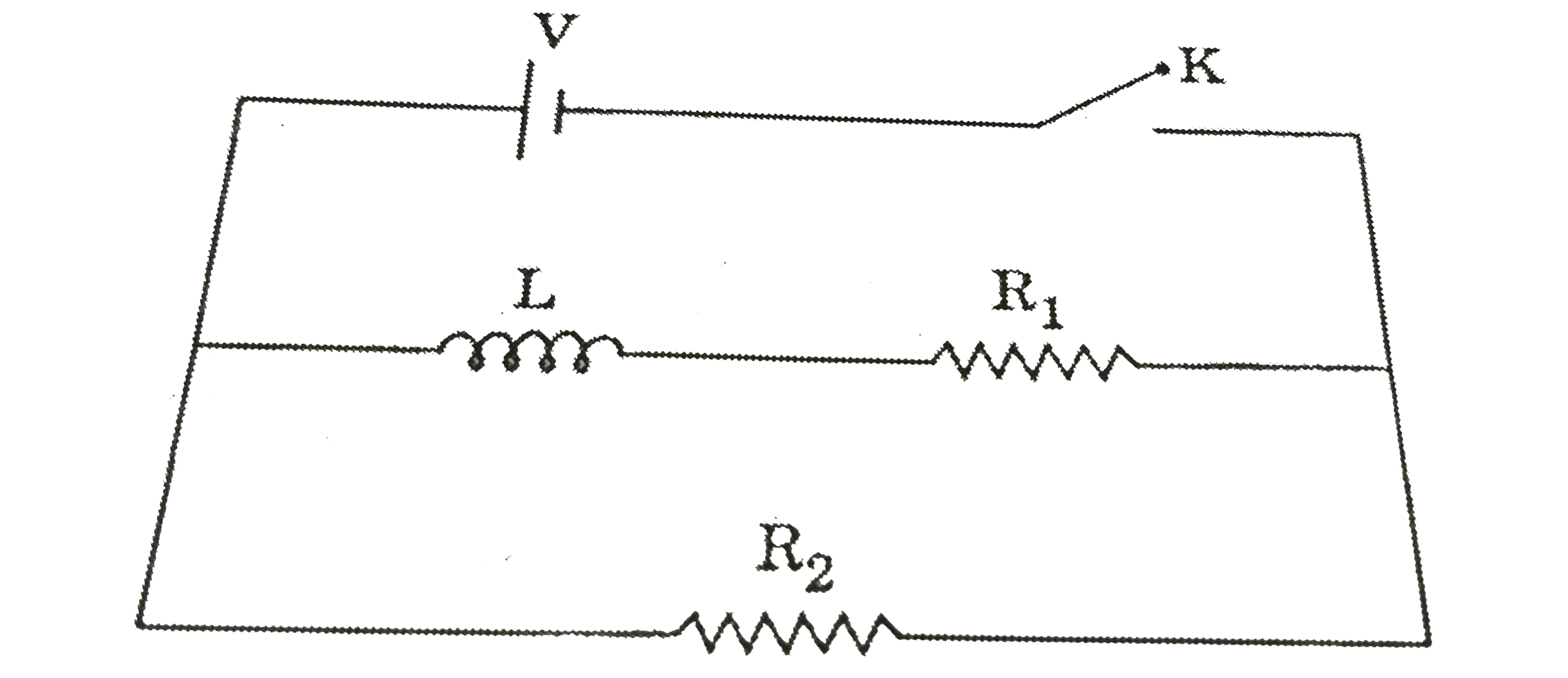
View SolutionIn the circuit shown below, the key K is closed at t = 0 . The current through the battery is
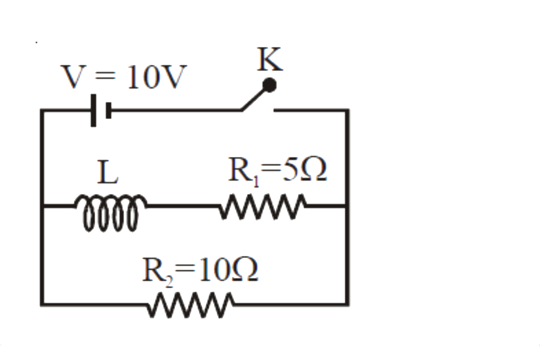
View SolutionChoose the correct statement w. r.t. RuBisCO
View Solution

