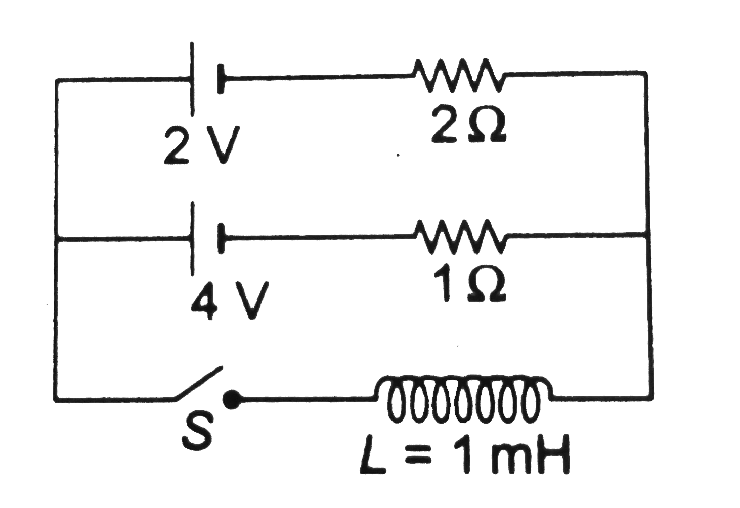
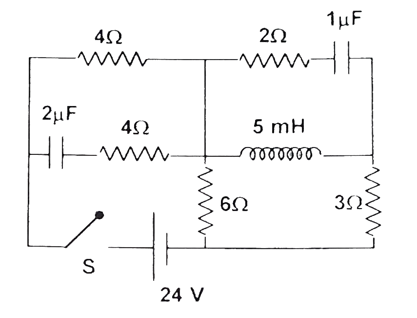
In the given circuit, the switch S is closed at time t = 0, then select the correct statement for current l in resistance PQ as shown in the figure. _PHY_E05_045_Q01.png)
l =20mA for all time t
l =10 mA for all time t
l = 20 mA at t = 0 and with it goes to 10 mA
l oscillates between 10 mA and 20 mA
Step by step video & image solution for In the given circuit, the switch S is closed at time t = 0, then select the correct statement for current l in resistance PQ as shown in the figure. by Physics experts to help you in doubts & scoring excellent marks in Class 12 exams.
Topper's Solved these Questions
Similar Questions
Knowledge Check
- Question 1 - Select One or More
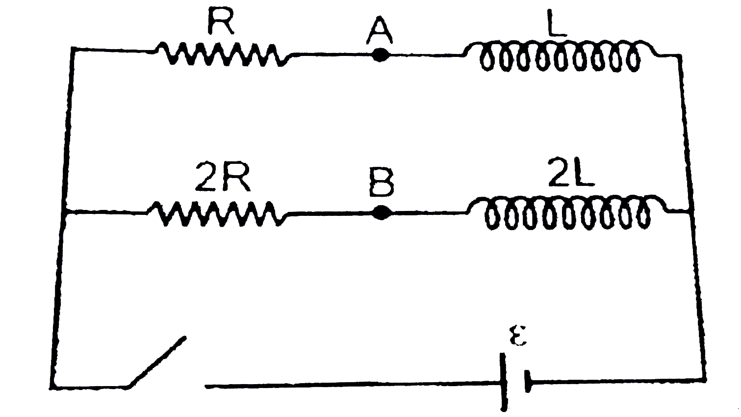
In given LR circuit the switch S is closed at time t=0 thenAThe ratio of induced emfs in the inductors of inductance L and 2L will be constantBThe ratio of induced emfs in the inductor of inductance L and 2L will be time varyingCthe potential difference VA−VB increases with timeDThe potential difference VA−VB will be constant - Question 2 - Select One or More
In the given circuit Fig the switch is closed at t=0. Choose the correct answers.
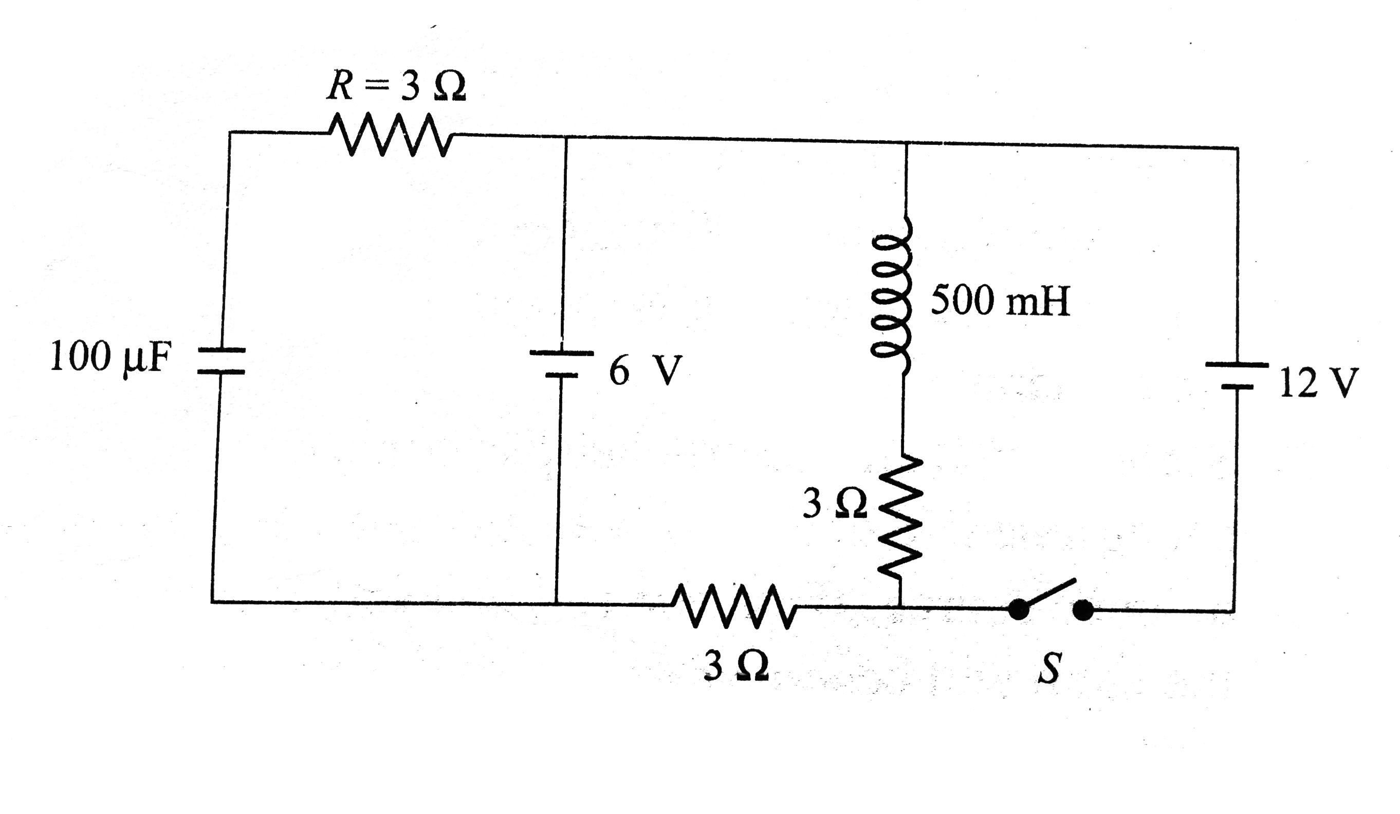 ACurrent in the inductor when the circuit reaches the steady state is 4A.BThe net change in flux in the inductor is 1.5Wb.CThe time constant of the circuit after closing S is 555.55sDThe charge stored in the capacitor in steady state is 1.2mC.
 - Question 3 - Select One or More
In the circuit shown in the figure, switch S is closed at time t=0. Select the correct statements.
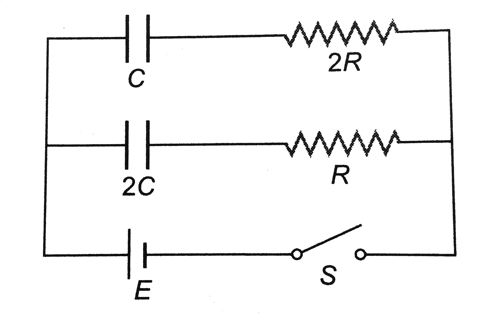 ARate of increase of charge is same in both the capacitorsBRatio of charge stored in capacitors C and 2C at any time t would be 1:2CTime constants of both the capacitors are equalDSteady state chares on capacitors C and 2C are in the ratio of 1:2
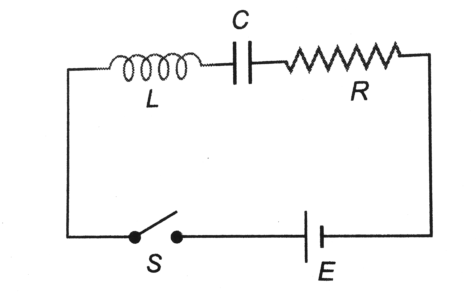
When the switch S is closed at t=0, identify the correct statement just after closing the switch as shown in figure
 View Solution
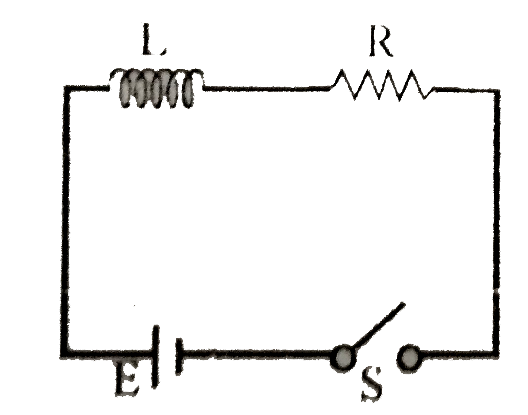
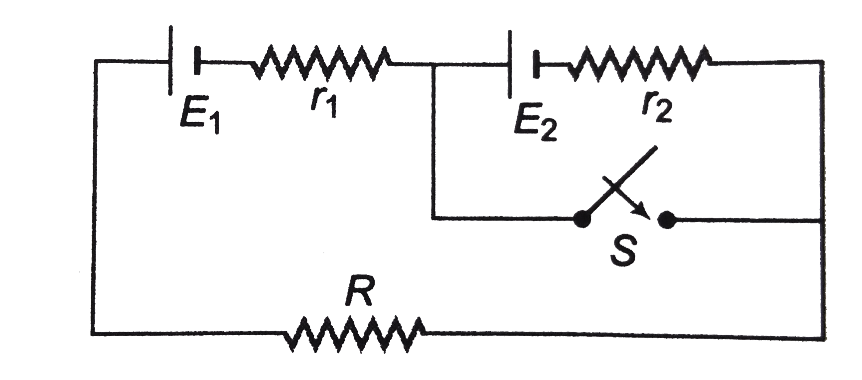
In the LR circuit as shown in figure, te switch is closed at t=0, mark the incorrect statement of the followingView SolutionSwitch S is closed at time t=0. Which one of the following statements is correct?
 View Solution
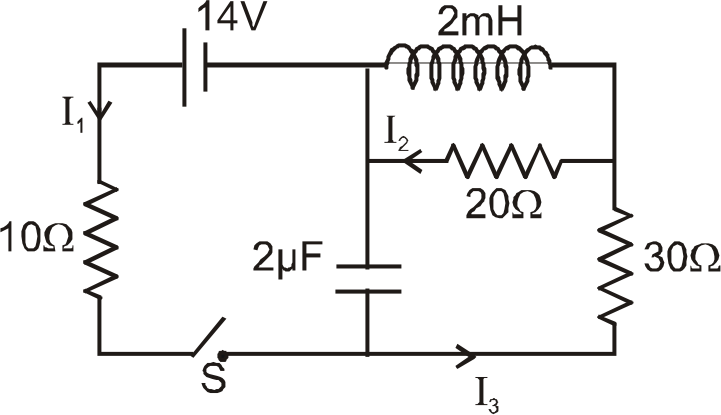
In the circuit shown, the switch is closed at t=0, the currents I1,I2 and I3 are
 View Solution
In the circuit shown, the switch 'S' is closed at t=0. Then the current through the battery steady state reached is
 View Solution


_PHY_E06_157_Q01.png)
