In the given circuit V01 and V02 are -

11.3 V & 0.3 V
0.3 V & 11.3 V
11.3 V & 11.3 V
0.3 V & 0.3 V
The correct Answer is:A
Step by step video & image solution for In the given circuit V_(0_1) " and " V_(0_2) are - by Physics experts to help you in doubts & scoring excellent marks in Class 12 exams.
Updated on:21/07/2023Topper's Solved these Questions
- SEMI CONDUCTOR AND LOGIC GATESBook:MOTIONChapter:SEMI CONDUCTOR AND LOGIC GATESExercise:EXERCISE 3
Explore 34 Videos
- SEMI CONDUCTOR AND LOGIC GATESBook:MOTIONChapter:SEMI CONDUCTOR AND LOGIC GATESExercise:EXERCISE 3
Explore 34 Videos
- ROTATIONAL MOTION Book:MOTIONChapter:ROTATIONAL MOTION Exercise:Exercise - 3 ( Section-B )
Explore 24 Videos
- SIMPLE HARMONIC MOTIONBook:MOTIONChapter:SIMPLE HARMONIC MOTIONExercise:EXERCISE -3 Section - B Previous Year Problems | JEE MAIN
Explore 23 Videos
Similar Questions
Knowledge Check

In the given circuit VO1&VO2 areA11.3 V 0.3 VB0.3 V & 11.3 VC11.3 V & 11.3 VD0.3 V & 0.3 VA resistor R is connected in series with a coil. The system is subjected to an AC supply of peak voltage V0. If the peak voltages dropped across the resistor R and the coil are V1 and V2 respectively
(a) The powerr dissipated in the coil is
V20−V21−V222R
The power dissipated in the circuit is
V20+V21−V222R
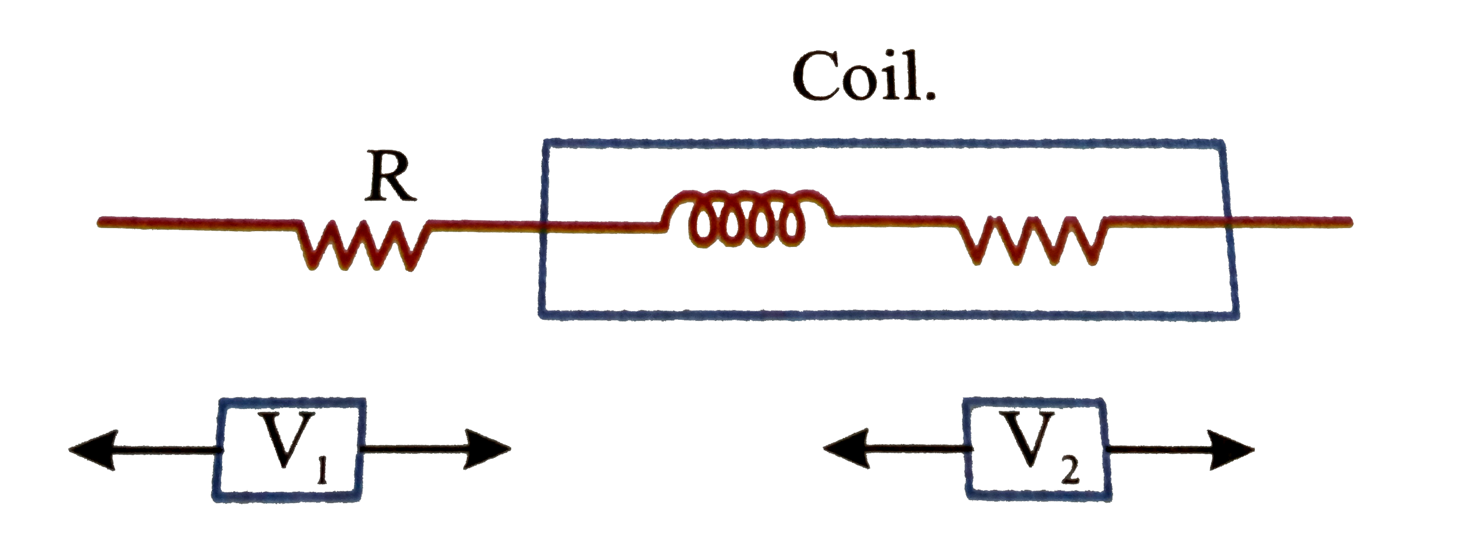 AOnly (a) is correctBOnly (b) is correctC(a),(b) are wrongD(a),(b) are correct
In an LCR series circuit, the reading of ideal voltmeters V1 and V2 are 20√2 volt and 15 volts respectively as shown in the figure (the given circuit in inductive in nature). Then
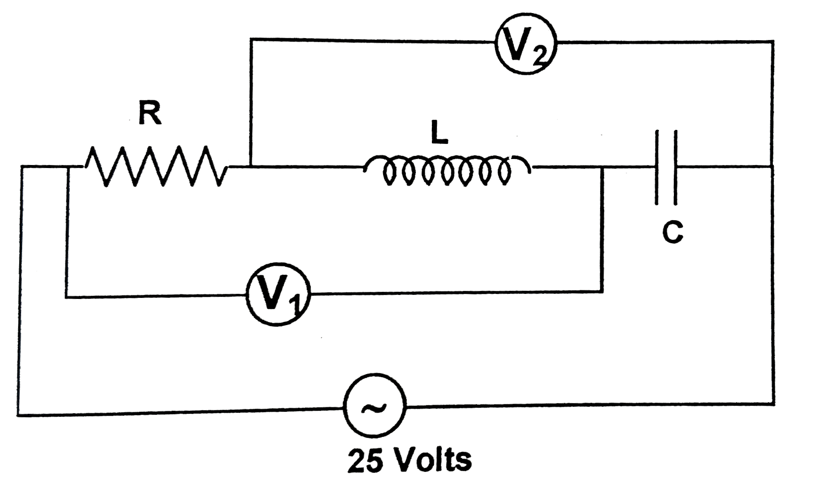 AThe voltage across resistor is 20 voltsBThe voltage across inductor is 20 voltsCThe voltage across capacitor is 5 voltsDThe power factor of the circuit is 45
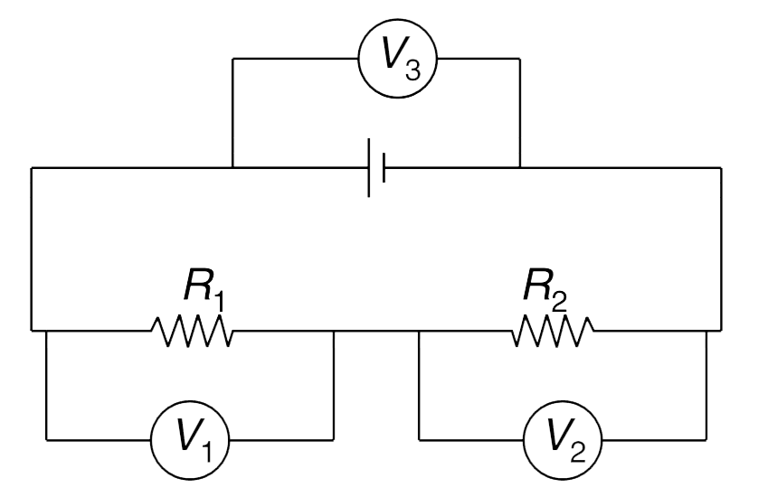
In the circuit shown in the figure, two resistors R1andR2 have been connected in series to an ideal cell. When a voltmeter is connected across R1 its reading is V1=4.0 volt and when the same voltmeter is connected across R2 its reading is V2=6.0 volt. The reading of the voltmeter when it is connected across the cell is V3=12.0 volt. Find the actual across R1 in the circuit.
View SolutionIn a common emitter circuit, if VCE is changed by 0.2 V, then collector current changed by 4×10⁻³mA. Output resistance will be-
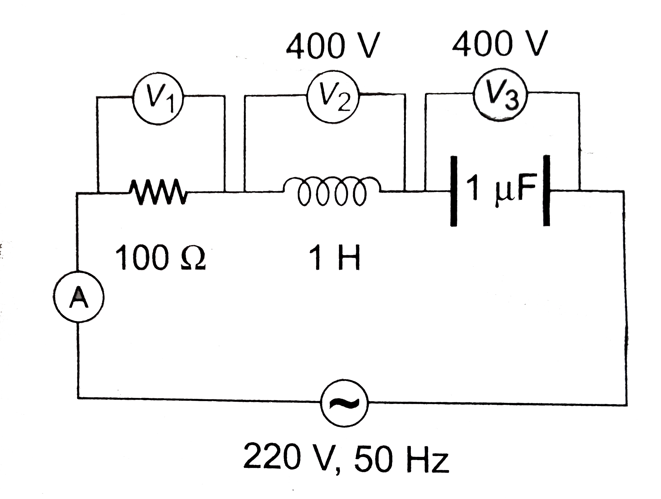
View SolutionIn the given circuit the readings of the voltmeter V1 and the ammeter A are
 .
.
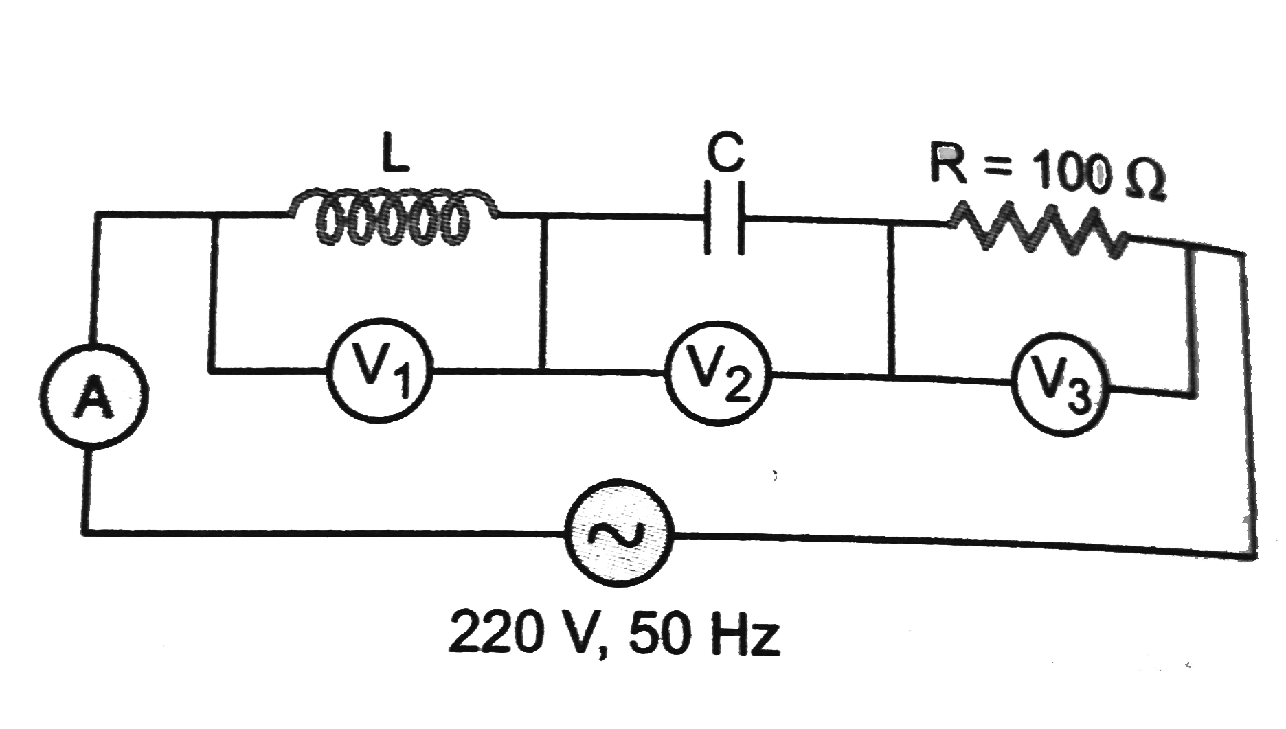
View SolutionIn the given circuit, Fig., the reading of voltmeter V1 and V2 300 votls each. The reading of the voltemeter V3 and ammeter A are respectively
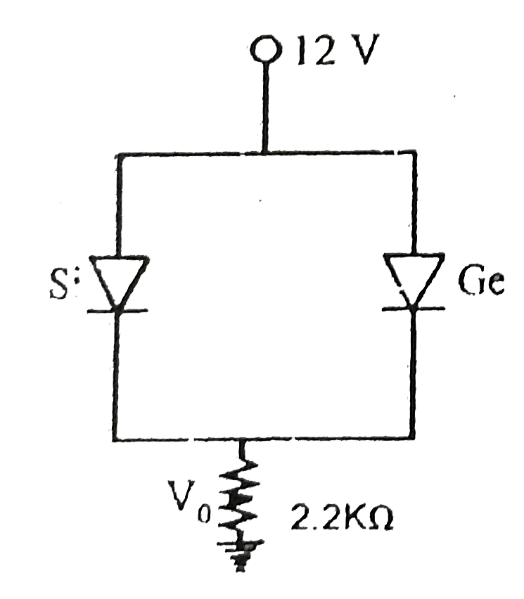
View SolutionIn the circuit shown in figure, Voltage V0 is
View Solution

_PHY_E06_148_Q01.png)