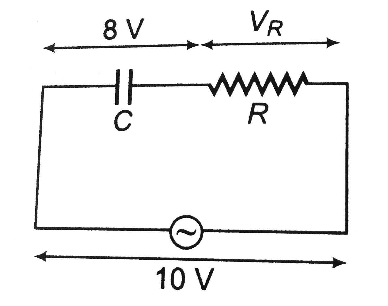
In a series C−R circuit shown in figureure, the applied voltage is 10V and the voltage across capacitor is found to8V. The voltage across R, and the phase difference between current and the applied voltage will respectively be
 .
.
6V,tan−1(43)
3V,tan−1(34)
6V,tan−1(53)
none
The correct Answer is:A
Step by step video & image solution for In a series C-R circuit shown in figureure, the applied voltage is 10 V and the voltage across capacitor is found to8 V. The voltage across R, and the phase difference between current and the applied voltage will respectively be . by Physics experts to help you in doubts & scoring excellent marks in Class 12 exams.
Updated on:21/07/2023Topper's Solved these Questions
- ALTERNATING CURRENTBOOK - MOTIONCHAPTER - ALTERNATING CURRENTEXERCISE - EXERCISE - 2 (LEVEL - I)
19 Videos
- ALTERNATING CURRENTBOOK - MOTIONCHAPTER - ALTERNATING CURRENTEXERCISE - EXERCISE - 2 (LEVEL - II)
5 Videos
- ALTERNATING CURRENTBOOK - MOTIONCHAPTER - ALTERNATING CURRENTEXERCISE - EXERCISE - 4 (LEVEL - II)
14 Videos
- 10 ROTATIONALBOOK - MOTIONCHAPTER - 10 ROTATIONALEXERCISE - Exercise - 4 (Level - II)
49 Videos
- ATOMIC STRUCTURE & X-RAY BOOK - MOTIONCHAPTER - ATOMIC STRUCTURE & X-RAY EXERCISE - Exercise - 2
31 Videos
Similar Questions
In a series CR circuit shown in figure,the applied voltage is 10V and the voltage across capacitor is found to be 8V
View SolutionIn a series CR circuit shown in the figure, the applied voltuge is 10V and the voltage across capacitor is found to be 8V. If the phase difference betweeni cutrent and the applied voltage will be tan−1(pq), then find pq.
'(##CEN_KSR_PHY_JEE_C24_E01_016_Q06##)'
View Solution
Knowledge Check
In series LCR circuit, the phase difference between voltage across L and voltage across C is
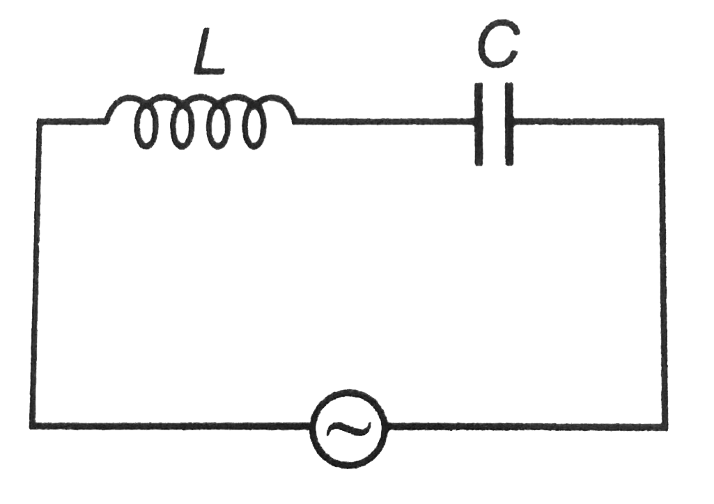
AZeroBπCπ2D2πIn a series L−C circuit, the applied voltage is V0. if omega is very low, then the voltage drop across the inductor VL and capacitor VC are
 .AVL=V02,VC=V02BVL=0,VC=V0CVL=V0,VC=0DVL=−VC=V02
In a LCR series circuit, if the phase difference between applied voltage and current is zero then
AXL=XCBXL>XCCXL<XCDnone of these
In an L-R circuit, an inductance of 0.1 H and a resistance of 1Ω are connected in series with an ac source of voltage V = 5 sin 10 t. The phase difference between the current and applied voltage will be
View SolutionIn an L-R circuit, an inductance of 0.1 H and a resistance of 1Ω are connected in series with an ac source of voltage V = 5 sin 10 t. The phase difference between the current and applied voltage will be
View SolutionIn an L-C-R circuit, if V is the effective value of the applied voltage VR is the voltage across R, VL is the effective voltage across L, VC is the effective voltage across C, then
View SolutionIn a series L−C−R circuit, currenrt in the circuit is 11A when the applied voltage is 220V. voltage across the caspcitor is 200V. If the value of resistor is 20Ω, then the voltage across the unknown inductor is
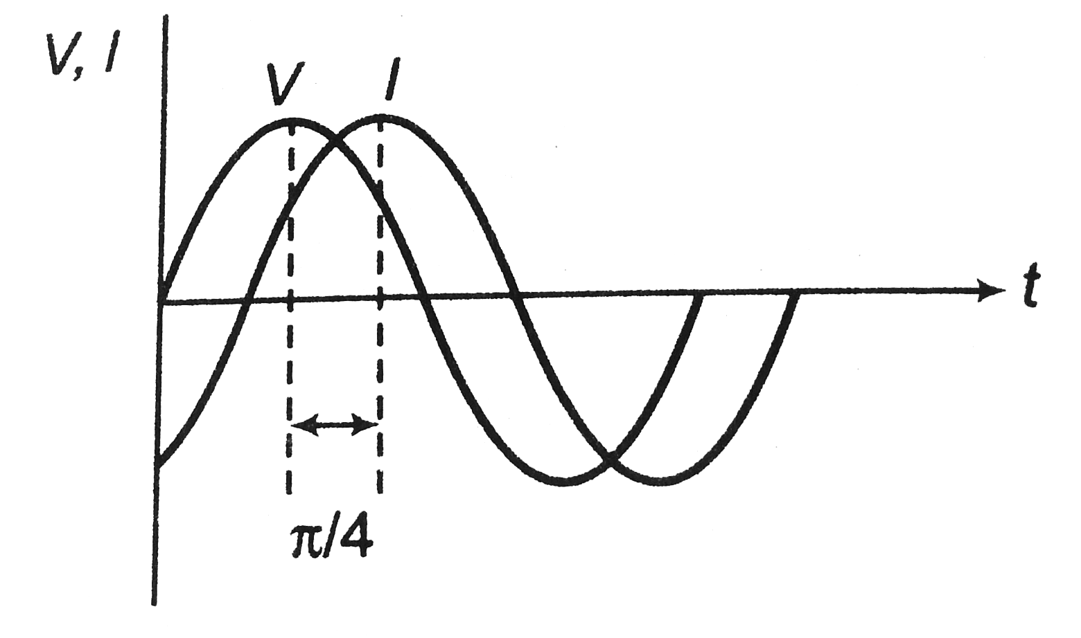
View SolutionAn Ac voltage V=V0sin100t is applied to the circuit, the phase difference between current and voltage is found to be π4, then
 .
.
View Solution
