Three block 1, 2 and 3 are arranged as shown in the figure. The velocities of the blockes v1 , v2 and v3 are shown in the figure. What is the relationship between v1 , v2 and v3 ?
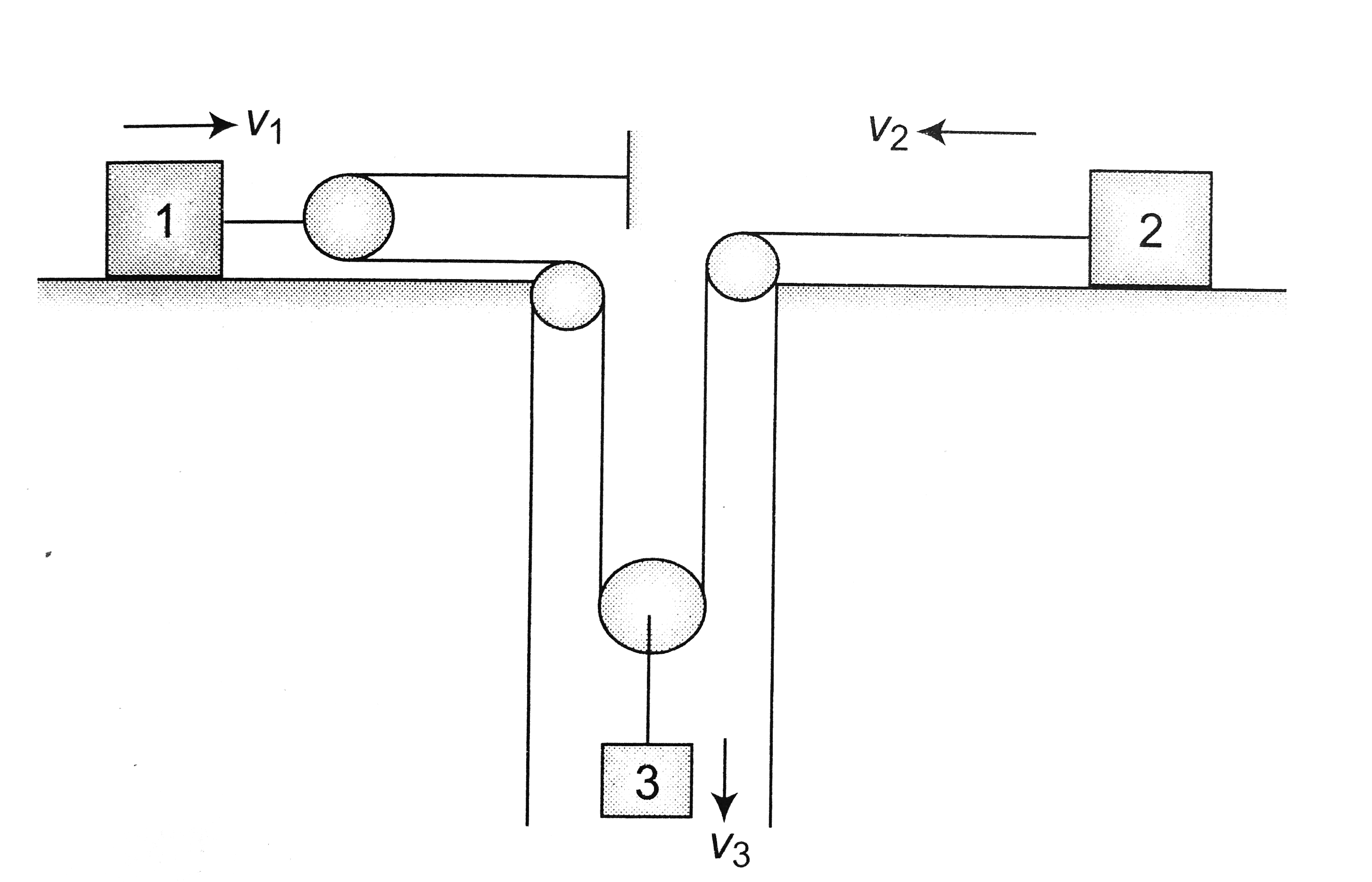
2v1+v2=v3
v1+v2=v3
v1+2v2=v3
None of these
The correct Answer is:D
Step by step video & image solution for Three block 1, 2 and 3 are arranged as shown in the figure. The velocities of the blockes v_(1) , v_(2) and v_(3) are shown in the figure. What is the relationship between v_(1) , v_(2) and v_(3) ? by Physics experts to help you in doubts & scoring excellent marks in Class 12 exams.
Updated on:21/07/2023Topper's Solved these Questions
- NLM & FRICTIONBOOK - MOTIONCHAPTER - NLM & FRICTIONEXERCISE - EXERCISE-2
66 Videos
- NLM & FRICTIONBOOK - MOTIONCHAPTER - NLM & FRICTIONEXERCISE - EXERCISE-2(Level-II)
25 Videos
- NLM & FRICTIONBOOK - MOTIONCHAPTER - NLM & FRICTIONEXERCISE - SOLVED EXAMPLE
16 Videos
- NEWTON'S LAWS OF MOTION & FRICTION BOOK - MOTIONCHAPTER - NEWTON'S LAWS OF MOTION & FRICTION EXERCISE - Exercise - 3 Section-B
12 Videos
- ONE DIMENSION MOTIONBOOK - MOTIONCHAPTER - ONE DIMENSION MOTIONEXERCISE - Exercise - 3 |Section - B Previous Year Problems | JEE MAIN
12 Videos
Similar Questions
Knowledge Check
In the arrangement shown in figure the ratio of velocity V1&V2 of block (1)&(2) is
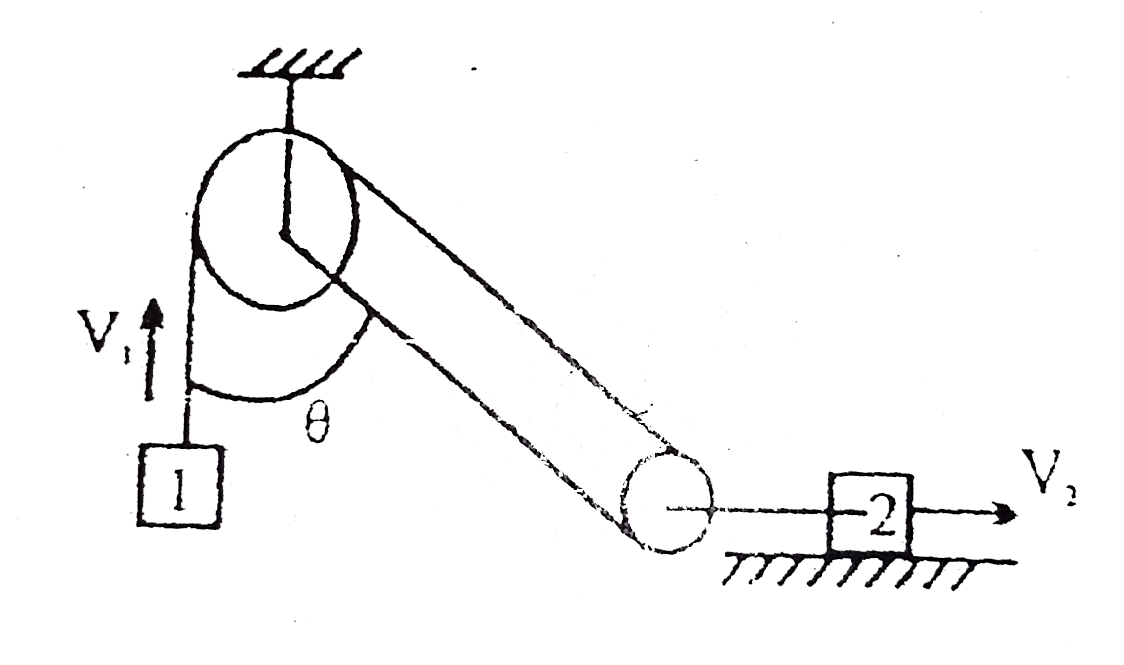 AV1V2=2cotθBV1V2=sinθ2CV1V2=2sinθDnone
In the given figure, the velocity v3 will be
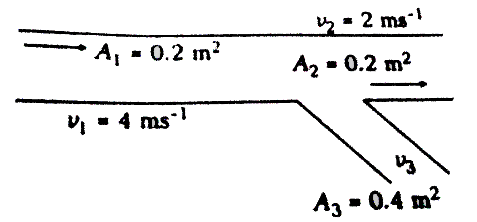 A2ms−1B4ms−1C1ms−1D3ms−1
A system changes from the state (P1,V1) to (P2,V2) as shown in the figure below. What is the work done by the system –
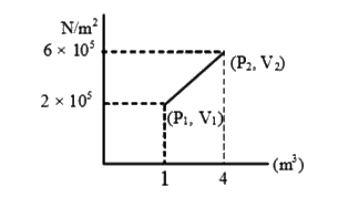 A7.5×105 jouleB7.5×104 ergC12×105 jouleD6×105 joule
Three capacitors C1,C2 and C3 are connected as shown in, The potentials of P,Q, and R are V1,V2, and V3, respectively. Find the potential V0 at the functionO.
 .
.
View SolutionIn the figure block moves downwards with velocity v1, the wedge rightwards with velocity v2. The correct relation between v1 and v2 is
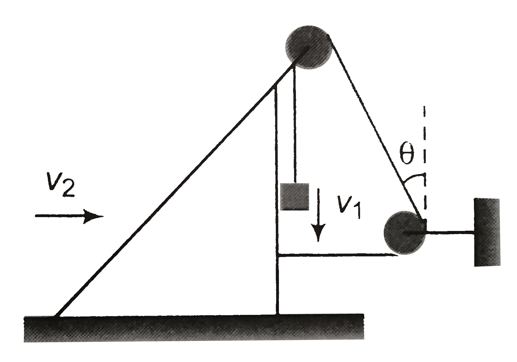
View SolutionThree uncharged capacitors of capacities C1,C2 and C3 are connected as shown in the figure to one another and the potentials V1,V2 and V3 respectively. Then the potential at O will be
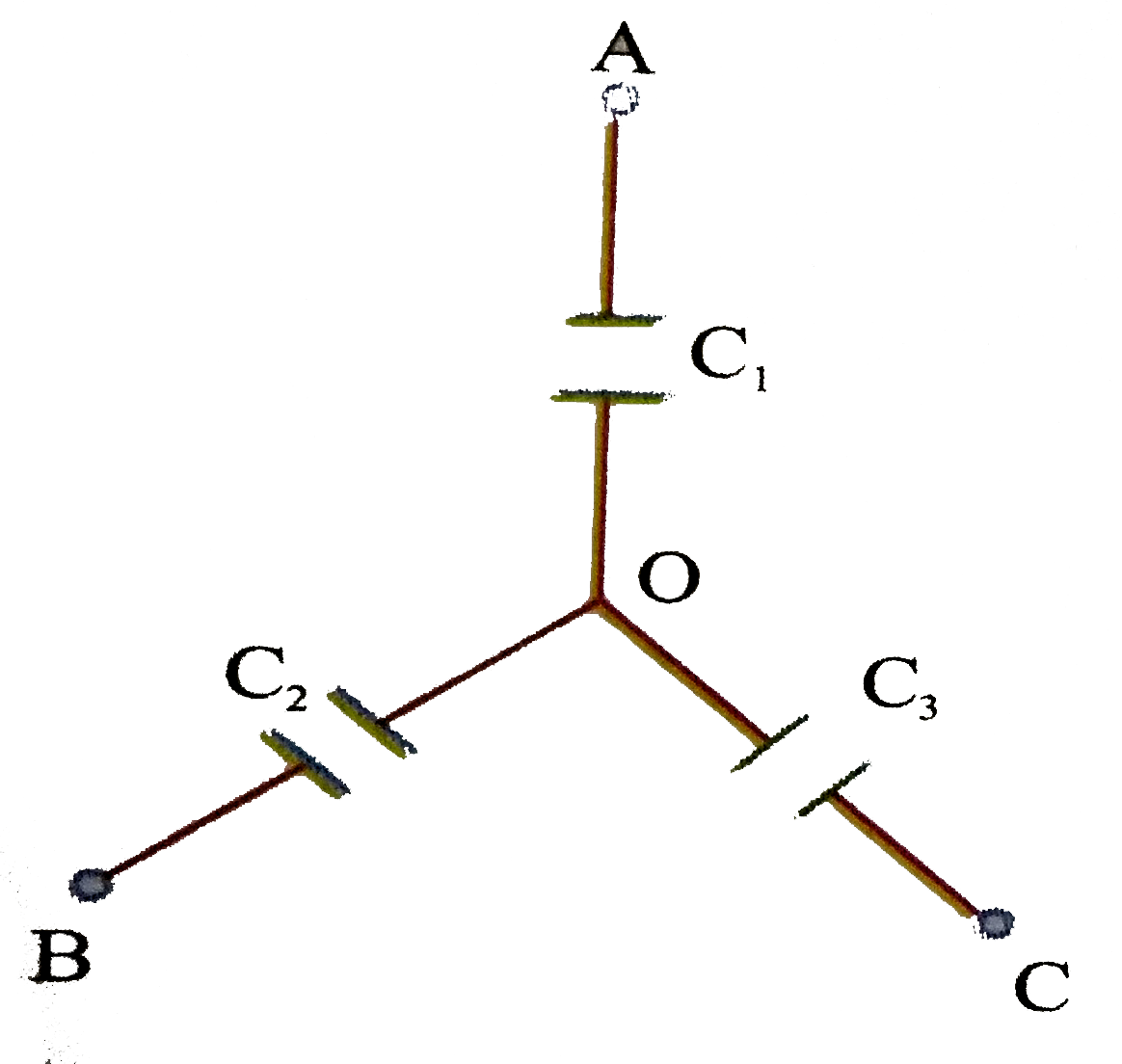 .
.
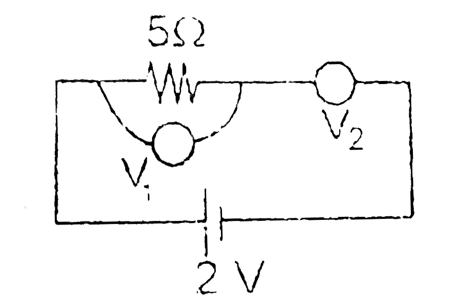
View SolutionConsider the circuit shown in the figure, the cell is ideal. The readings of the ideal voltmeters V1 and V2 in volts are respectively.
View SolutionThe frequencies for series limit of Balmer and Paschen series respectively are v1 and v3. If frequency of first line of Balmer series is v2 then the relation between v1,v2 and v3 is
View Solution

