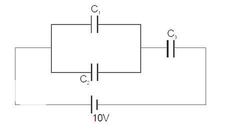
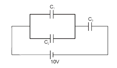
In the circuit shown the capacitors areC1=15μF,C2=10μFandC2=25μF.Find
(i) The equivalent capacitance of the circuit
(ii) The charge on each capacitor and
(iii) The potential difference a across each capacitor.
Text Solution
(i) (C1+C2)C3(C1+C2)+C3=(25×2525+25)μF=12.5μF
(##MOTCONJ∃PHYC25SLV017_S01.png width=80%><br>(ii)Q=Totalchar≥⊃pliedbythecell=CV= (12.5xx 10 ) mu C = 125 mu C <br>char≥on<br> C_1 = Q_1 = ((C_1)/((C_1+C_2)) Q= ( ( 15)/( 15+10 ) ) xx 125 = 75 muC <br>Char≥on<br> C_2 = Q_2 = ( ( C_2 )/( C_1+C_2)) Q= ( (10 )/( 15+ 10 )) xx 125 = 50 mu C <br>(iii)p.d.across C_1 = V_1 = (Q_1 )/(C_1 ) = ( 75)/( 15) = 5V <br>p.d.acrossC_2 =V_2 V-1 = 5V <br>p.d.across C_2 = V_2 =(Q_3)/(C_3) = (125)/( 25) = 5V
|
Topper's Solved these Questions
- Capacitance BOOK - MOTIONCHAPTER - Capacitance EXERCISE - EXERCISE -1
60 Videos
- Capacitance BOOK - MOTIONCHAPTER - Capacitance EXERCISE - EXERCISE -2
36 Videos
- CALORIMETRY BOOK - MOTIONCHAPTER - CALORIMETRY EXERCISE - EXERCISE - 3 Section - B
4 Videos
- CENTRE OF MASSBOOK - MOTIONCHAPTER - CENTRE OF MASSEXERCISE - Exercise - 4 Level-II
20 Videos
Similar Questions
Knowledge Check
In the circuit shown in figure find
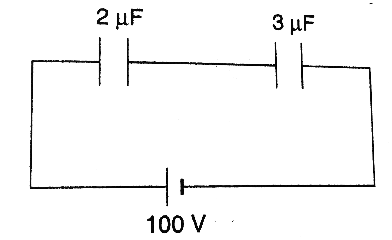
a. the equivalent capacitance
b. the charge stored in each capacitor and
c. the potential difference across each capacitor.A1.2μF 120μC 60Vand40VB1.2μF 120μC 60Vand20VC1.2μF 12μC 60Vand40VD12μF 120μC 60Vand40VIn the circuit shown in the figure, the potential difference across the 4.5μF capacitor is
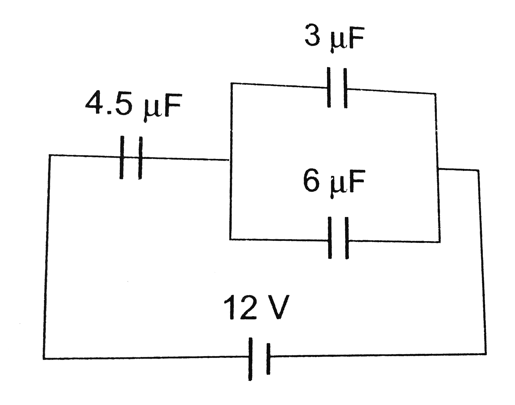 A8/3 voltB4 voltC6voltD8volt
In the circuit shown in the following the potential difference across the 3μF capacitor is
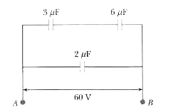
View SolutionIn the given circuit, the charge on 4μF capacitor will be :
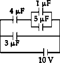
View SolutionThe equivalent capacitance of the combination between A and B in the given figure is 4μF .
What will be the potential drop across each capacitor ?

View SolutionIn the circuit shown , charge on the 5μF capacitor is :
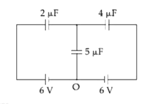
View SolutionIn the circuit shown , charge on the 5μF capacitor is :

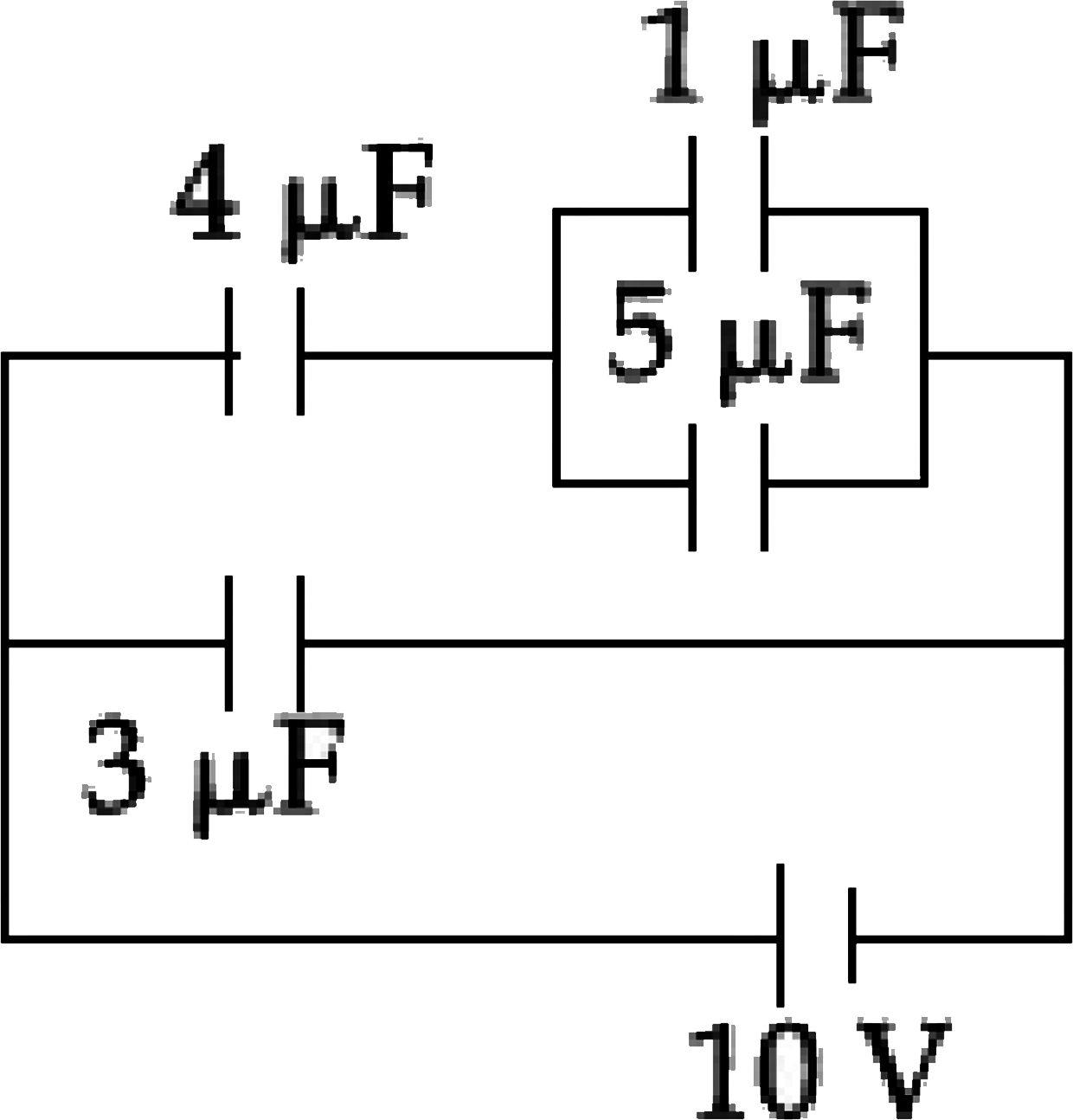
View SolutionIn the given circuit, the charge on 4μF capacitor will be :
 .
.
View Solution

