In the circuit shown initially are uncharged. After closing the switch
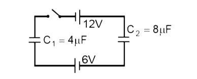
The charge on is greater that on
The charge on are the same
The potential drops across are the same
The potential drops across is greater than that across
The correct Answer is:B
Step by step video, text & image solution for In the circuit shown initially C_1, C_2 are uncharged. After closing the switch by Physics experts to help you in doubts & scoring excellent marks in Class 12 exams.
Topper's Solved these Questions
- BOOK - MOTIONCHAPTER - Capacitance EXERCISE - EXERCISE -2 LEVEL (II)22videos
Capacitance
- BOOK - MOTIONCHAPTER - Capacitance EXERCISE - EXERCISE -3 LEVEL 131videos
Capacitance
- BOOK - MOTIONCHAPTER - Capacitance EXERCISE - EXERCISE -160videos
Capacitance
- BOOK - MOTIONCHAPTER - CALORIMETRY EXERCISE - EXERCISE - 3 Section - B4videos
CALORIMETRY
- BOOK - MOTIONCHAPTER - CENTRE OF MASSEXERCISE - Exercise - 4 Level-II20videos
CENTRE OF MASS
Similar Questions
Knowledge Check
- Question 1 - Select One
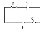
In the circuit shown, the capacitor is initially uncharged. The switch S is closed at t = 0. Time after which voltage across capacitor and resistor are equal is:
 ARCln12BRCln2CRCln32DRC
 - Question 2 - Select One
The two capacitors in the circuit shown in figure are initially uncharged and then connected as shown and switch is closed. What is the potential difference across 3μF capacitor?
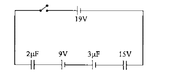 A30VB10VC25VDNone of these
 - Question 3 - Select One
The capacitor of capacitance C in the circuit shown in fully charged initially. Resistance is R.–
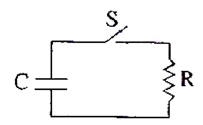
After the switch S is closed, the time taken to reduce the stored energy in the capacitor to half its initial value isARC/2B2RC in 2CRC ln 2DRCln22
The capacitor C1 in the figure shown initially carries a charge q0. When the switches S1 and S2 are closed, capacitor C1 is connected in series to a resistor R and a second capacitor C2 which is initially uncharged.
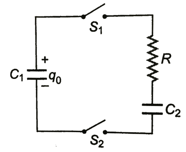
The charge flown through wires as a function of time is
where C=C1C2C1+C2View SolutionThe capacitor C1 in the figure shown initially carries a charge q0. When the switches S1 and S2 are closed, capacitor C1 is connected in series to a resistor R and a second capacitor C2 which is initially uncharged.
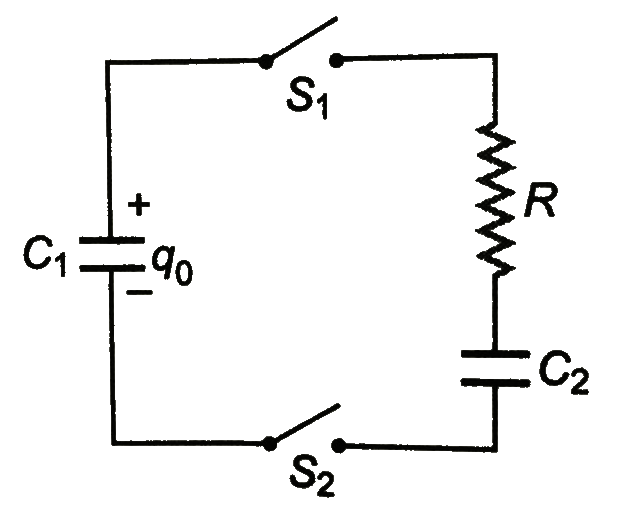
the total head dissipated in the circuit during the discharging process of C1 isView SolutionThe following two questions refer to the circuit shown. Assume that the capacitors are initially uncharged.
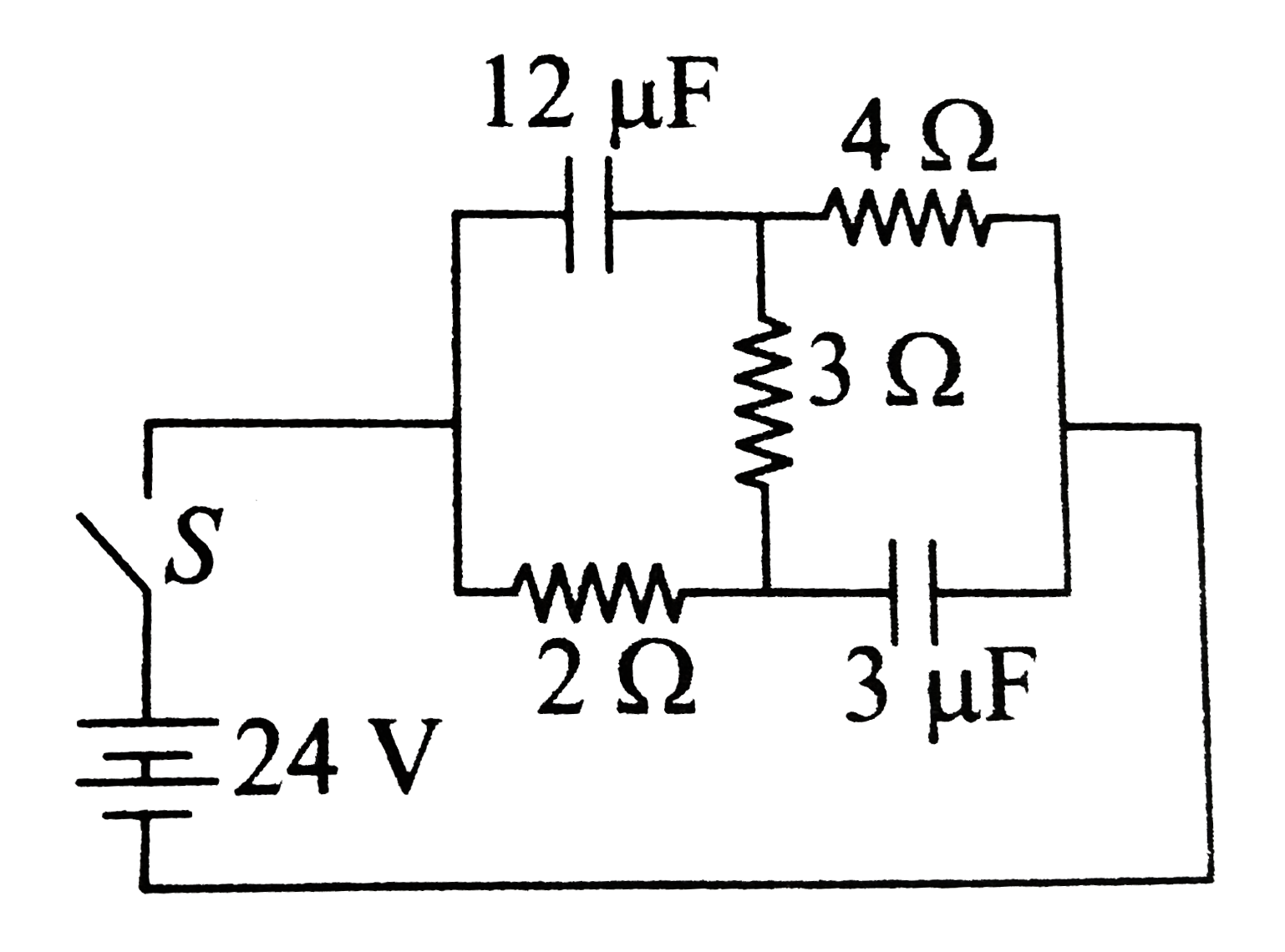
After the switch has been closed for a long time, how much charge is on the positive plate of the 3μF capacitor?View SolutionIn the circuit shown in, C1=6μF,C2=3μF, and battery B=20V. The switch S1 is first closed. It is then opened, and S2 is closed. What is the final charge on C2
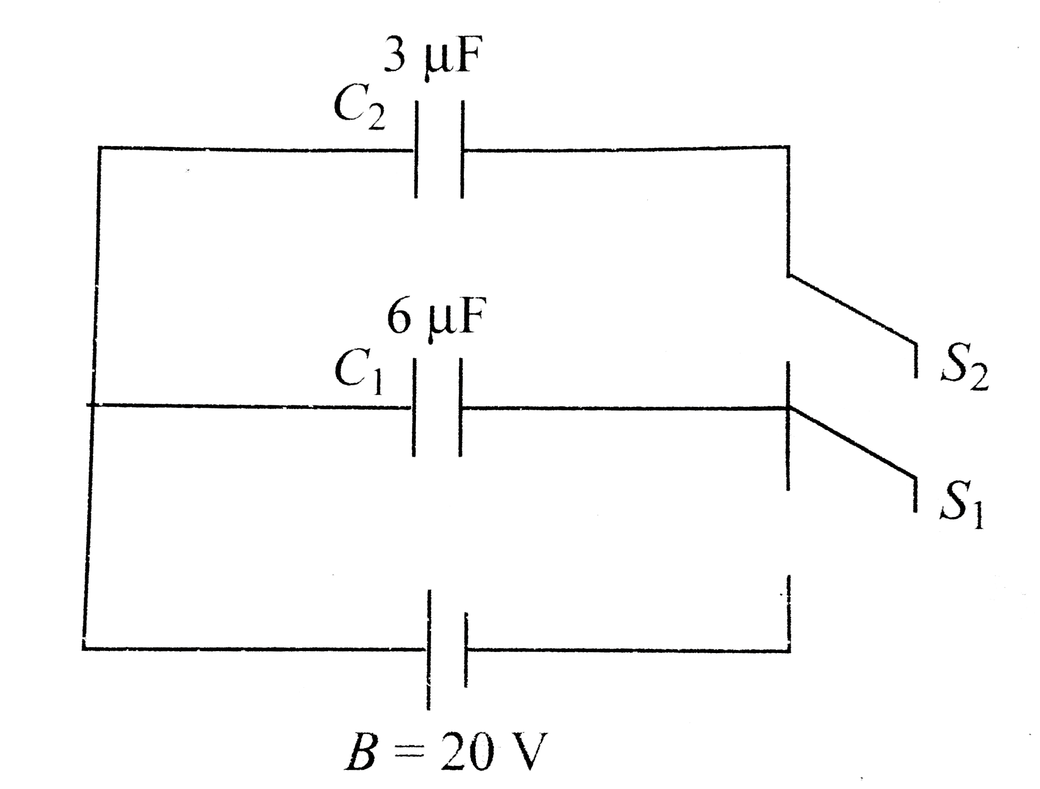 . View Solution
In the circuit shown in figure initially the switch is opened. The switch is closed now.
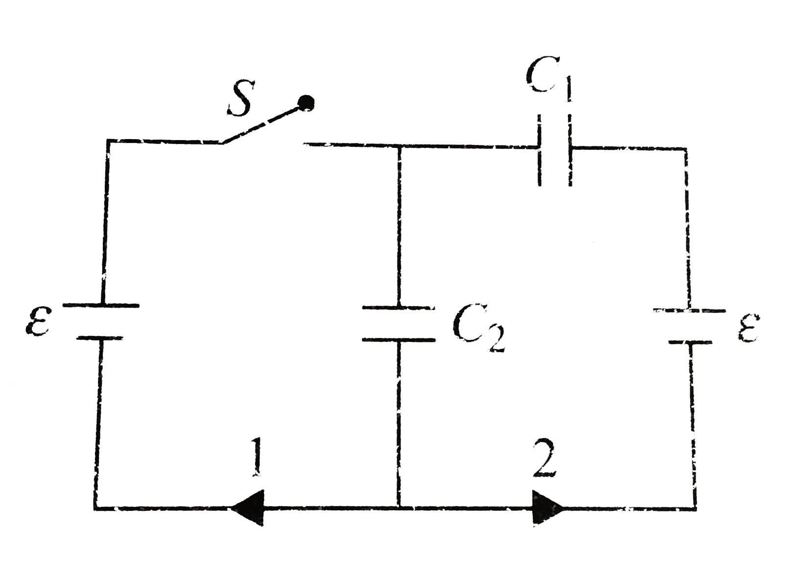
The charge that will flow in direction 1 isView Solution


