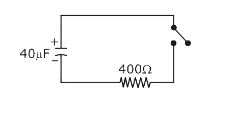
In the given circuit, At t = 0–, before the switch closed, V was measured as 100 V. If energy liberated in resistor in t second isk×10−1(1–e−125t), then find the value of k.
The correct Answer is:2
Step by step video & image solution for In the given circuit, At t = 0^(–), before the switch closed, V was measured as 100 V. If energy liberated in resistor in t second is k×10^(-1)(1–e-^(125)t), then find the value of k. by Physics experts to help you in doubts & scoring excellent marks in Class 12 exams.
Updated on:21/07/2023Topper's Solved these Questions
- Capacitance BOOK - MOTIONCHAPTER - Capacitance EXERCISE - EXERCISE -3 LEVEL II
17 Videos
- Capacitance BOOK - MOTIONCHAPTER - Capacitance EXERCISE - EXERCISE -4 LEVEL 1
15 Videos
- Capacitance BOOK - MOTIONCHAPTER - Capacitance EXERCISE - EXERCISE -2 LEVEL (II)
22 Videos
- CALORIMETRY BOOK - MOTIONCHAPTER - CALORIMETRY EXERCISE - EXERCISE - 3 Section - B
4 Videos
- CENTRE OF MASSBOOK - MOTIONCHAPTER - CENTRE OF MASSEXERCISE - Exercise - 4 Level-II
20 Videos
Similar Questions
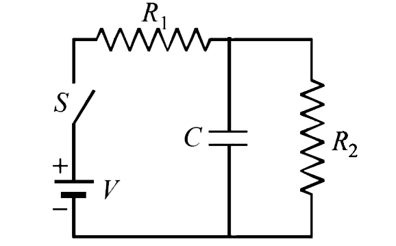
In the given circuit, the switch S is closed at time t = 0 . The charge Q on the capacitor at any instant t is given by Q(t)=Q(1−e−αt). Find the value of Q0 and α in terms of given parameters as shown in the circuit.
 .
.
View SolutionIn the circuit as shown in figure the switch is closed at t=0.
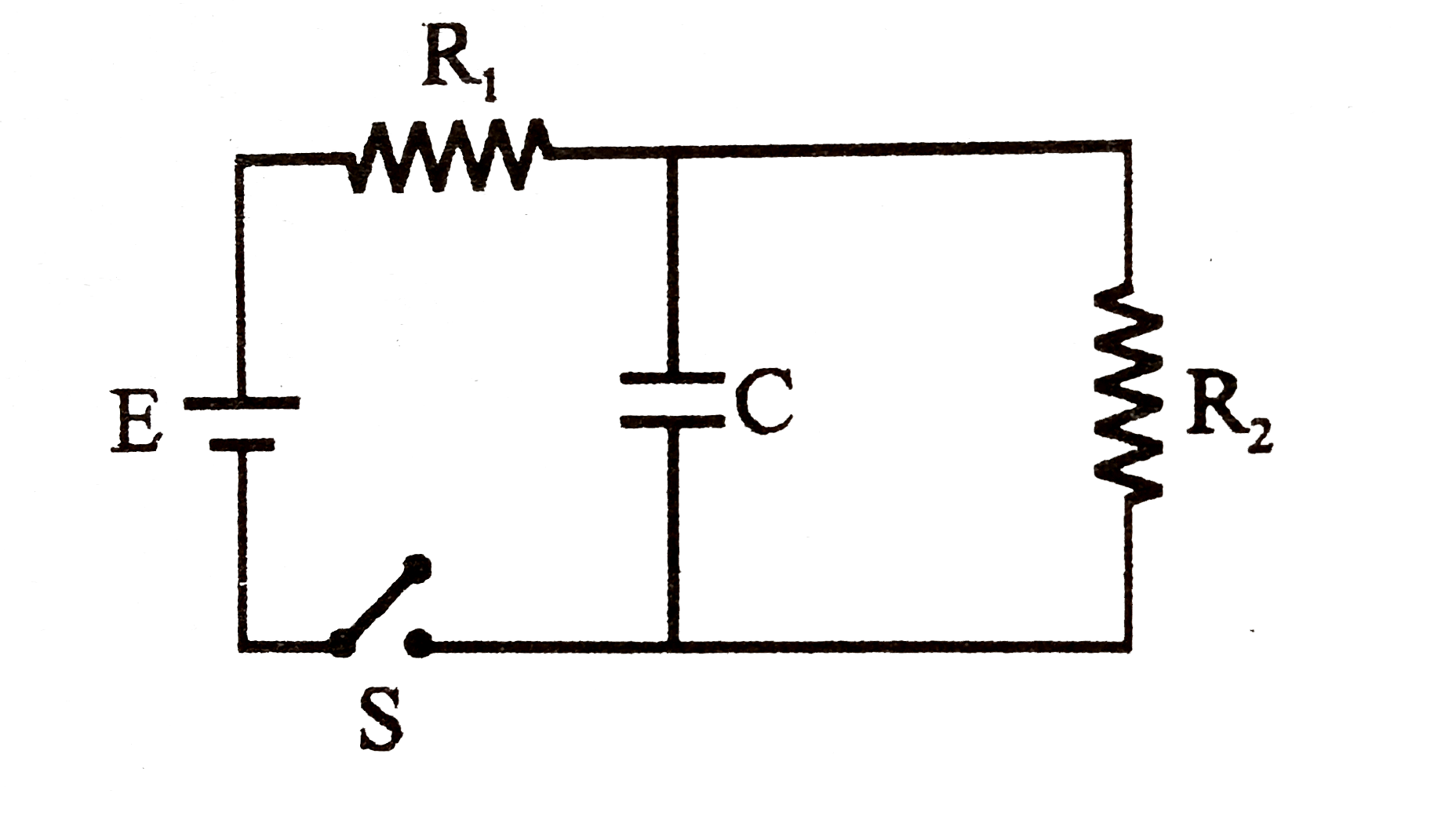
At the instant of closing the switch
View Solution
Knowledge Check
In the given circuit Fig the switch is closed at t=0. Choose the correct answers.
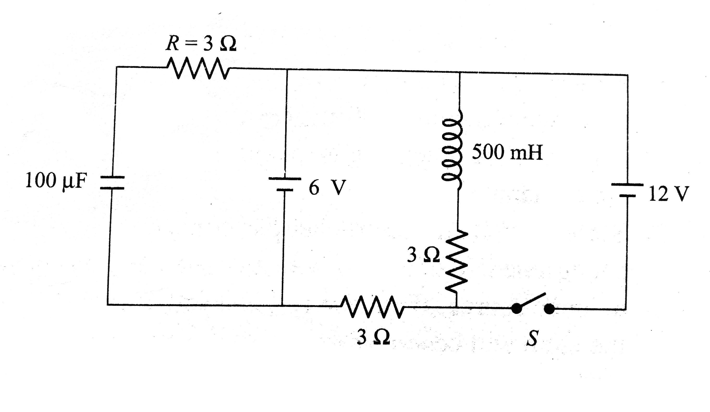 ACurrent in the inductor when the circuit reaches the steady state is 4A.BThe net change in flux in the inductor is 1.5Wb.CThe time constant of the circuit after closing S is 555.55sDThe charge stored in the capacitor in steady state is 1.2mC.
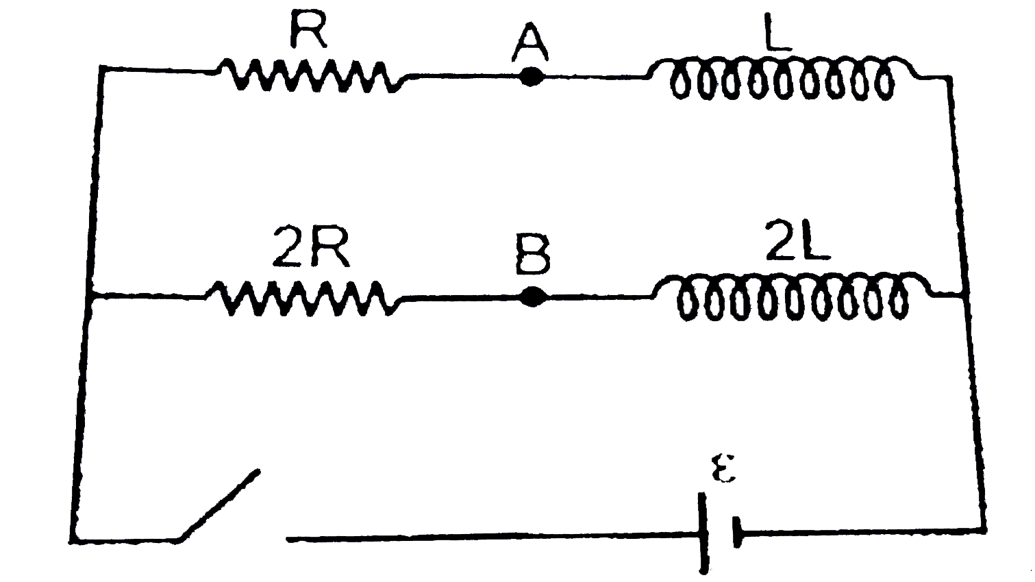
In given LR circuit the switch S is closed at time t=0 thenAThe ratio of induced emfs in the inductors of inductance L and 2L will be constantBThe ratio of induced emfs in the inductor of inductance L and 2L will be time varyingCthe potential difference VA−VB increases with timeDThe potential difference VA−VB will be constantIn the circuit shows in Fig the switch is closed at t=0.
 AAt t=0,I1=I2=0BAt any time t,I0I2=L2L1CAt any time t, I1+I2=εRDAt t=∞,I1 and I2 are independent of L1 and L2
In the circuit shown in figure switch S is closed at time t=0
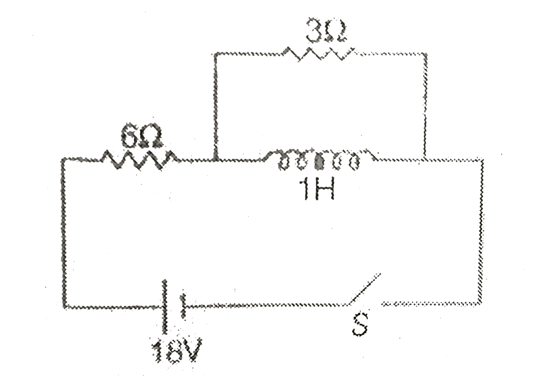
Current I from the battery at time t is given by
View SolutionIn the given at t=0, switch S is closed.
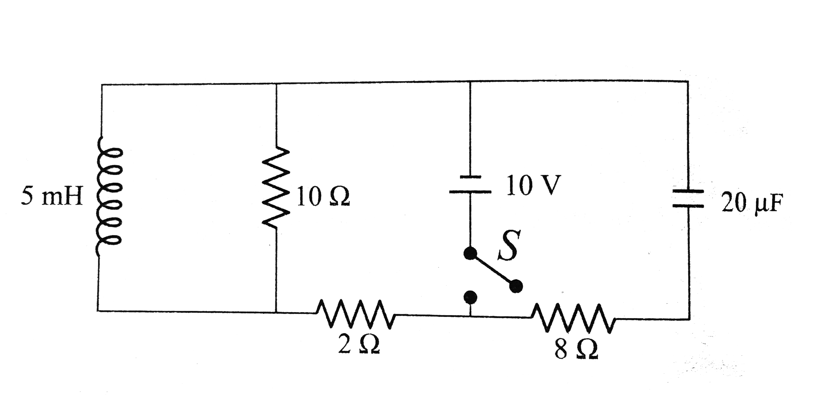
The current through the 10Ω resistor at any instant t(0<t<∞) will be
View SolutionIn the given at t=0, switch S is closed.
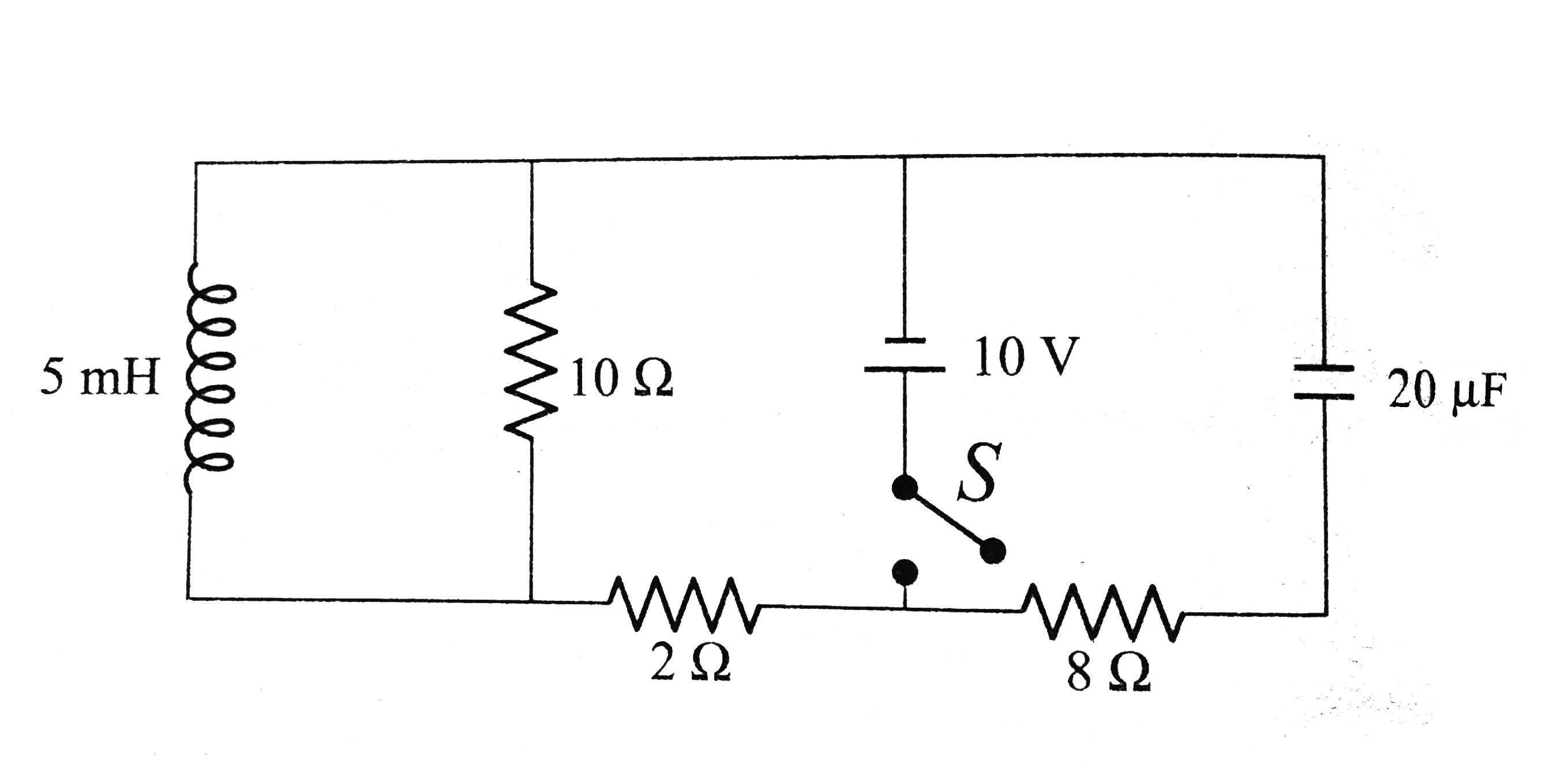
The energy stored in the inductor at any instant t(0<t∞) will be
View SolutionIn the given circuit switch is closed at t=0. The charge flown in time t=Tc (where Tc is time constant).
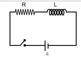
View Solutionthere in no current part of this circuit for time t<o. Switch S is closed at t=0.
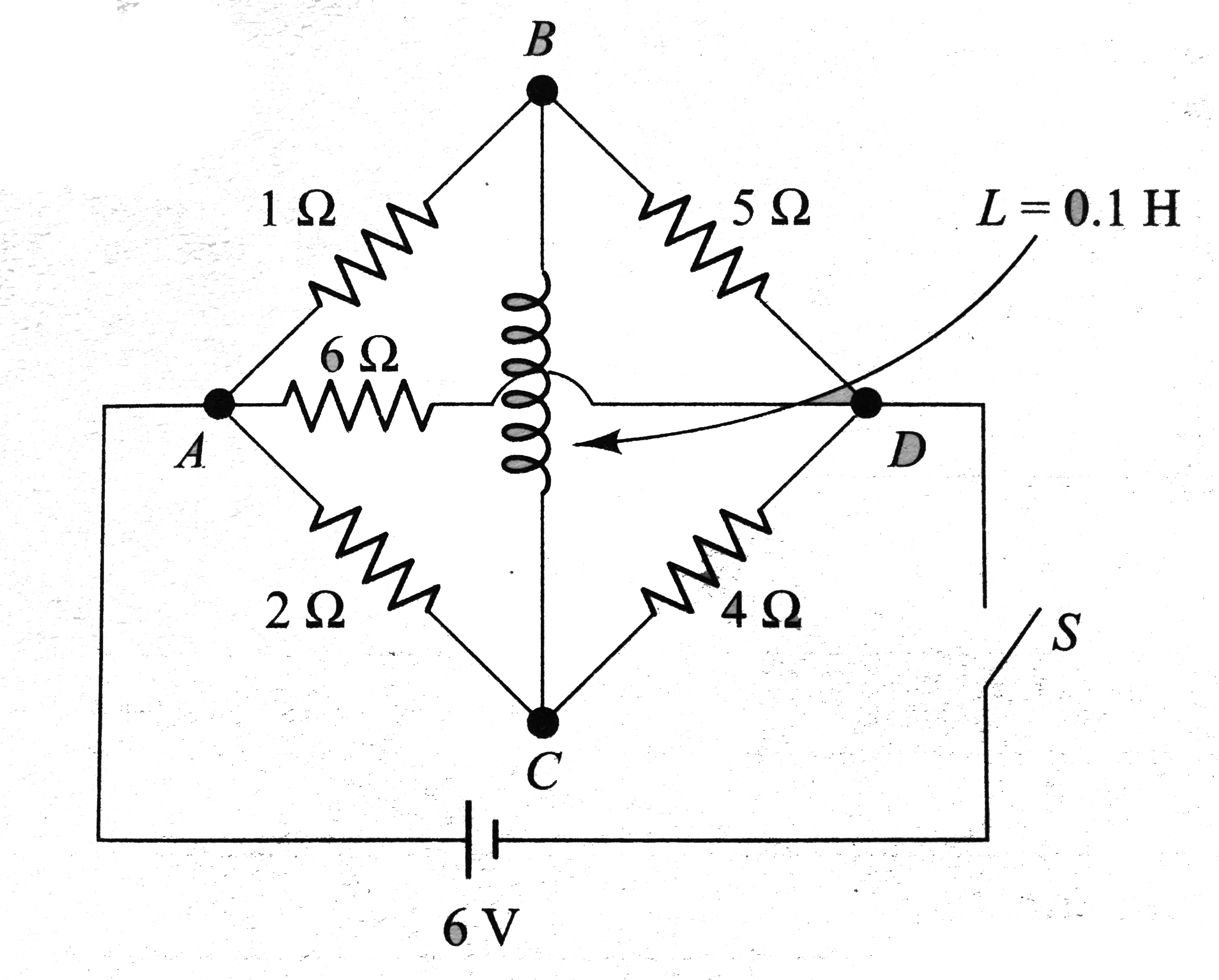
Current through the 6Ω resistor
View Solution
