Consider an infinte ladder network shown in figure. A voltage V is applied between the points A and B. This applied value of voltage is halved after each section.

R1/R2=1
R1/R2=1/2
R1/R2=2
R1/R2=3
The correct Answer is:B
Step by step video & image solution for Consider an infinte ladder network shown in figure. A voltage V is applied between the points A and B. This applied value of voltage is halved after each section. by Physics experts to help you in doubts & scoring excellent marks in Class 12 exams.
Updated on:21/07/2023Topper's Solved these Questions
- CURRENT ELECTRICITYBOOK - MOTIONCHAPTER - CURRENT ELECTRICITYEXERCISE - EXERCISE - 1 (SECTION E- Electrical Power & Energy)
10 Videos
- CURRENT ELECTRICITYBOOK - MOTIONCHAPTER - CURRENT ELECTRICITYEXERCISE - EXERCISE - 1 (SECTION F- Electrical Instrument + Exp. Verifying ohm s law & Specific Resistance Using Meter Brige & Post Office + Potentiomenter (EMF & Int . Res.)
11 Videos
- CURRENT ELECTRICITYBOOK - MOTIONCHAPTER - CURRENT ELECTRICITYEXERCISE - EXERCISE -1(SECTION B- Resistance & resistivity , Ohms law +VI (Volt - curr.) Characteristics + Colour Code + Temp . Dependence
8 Videos
- CONSTRAINED MOTION BOOK - MOTIONCHAPTER - CONSTRAINED MOTION EXERCISE - EXAMPLES
12 Videos
- ELASTICITYBOOK - MOTIONCHAPTER - ELASTICITYEXERCISE - EXERCISE -3
60 Videos
Similar Questions
Consider an infinite ladder of network as shown in the adjacent figure. A voltage is A applied between points A and B. If the voltage is halved after each section, find the ratio of R1/R2
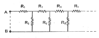
View SolutionConsider an infinita ladder of network shown In fig 5.223A voltage is applied between points A and B. If the voltage is havled after each seciton, find the raito of R1/R2

Suggest a method to terminate it after a few sections without introducing much error in its attenuation.
View Solution
Knowledge Check
In the circuit shown in figure, Voltage V0 is
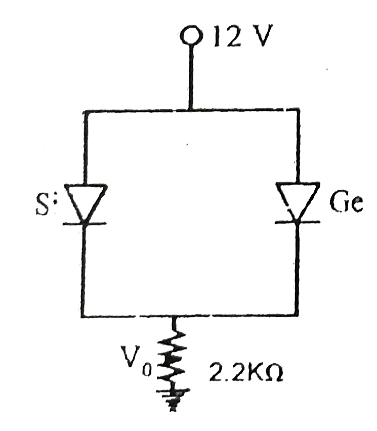 A11.7 voltB11.3 voltC0DNone
When an A.C voltage of 220V is applied to the capacitor C
AThe maximum voltage between plates is 220VBthe current is in phase with the applied voltageCthe change on the plates is in phase with the applied voltage.Dpower delivered to the capacitor is zero.
The voltage drop between the points A and B in the given figure is

View SolutionIn the circuit shown in figure, Voltage V0 is–
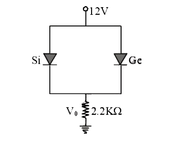
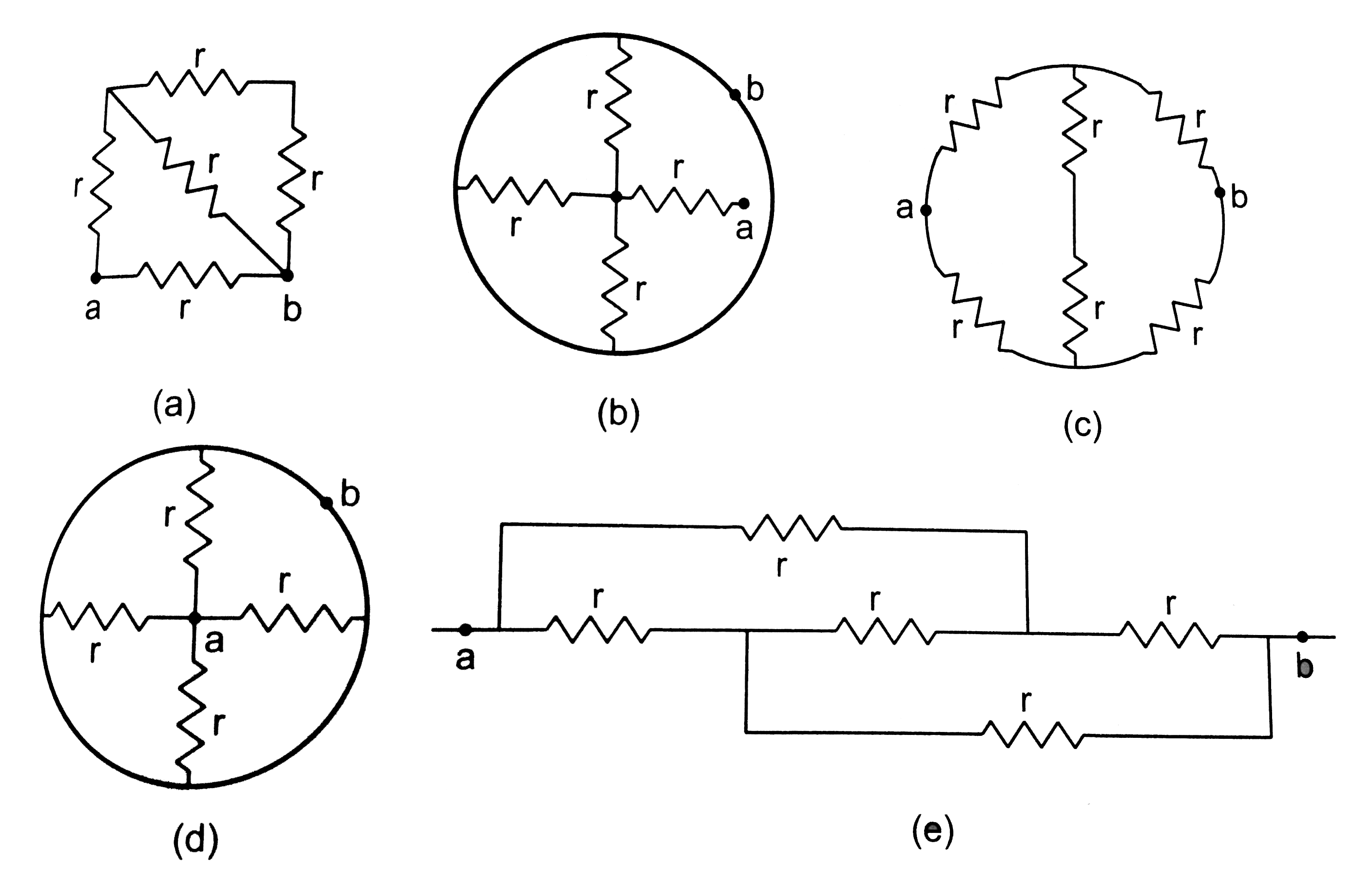
View SolutionFind the equivalent resistance of the network shown in figure between the points aandb.
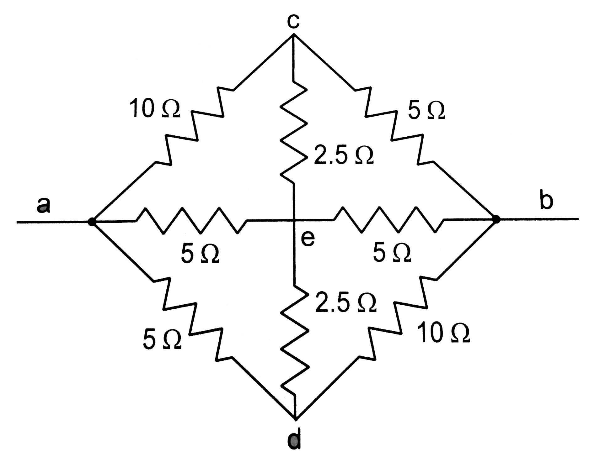
View SolutionFind the equivalent resistances of the network shown in figure between the point a and b.
View SolutionFind the equivalont capacitance of the infinite ladder shown in the figure (a) between the points A and B .

View SolutionFind the equivalent capacitance of the infinite ladder shown in figure between the points A & B.

View Solution
