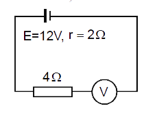
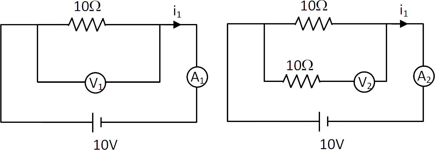
By error , a student places moving -coil voltmeter V (nearly ideal) in series with the resistance in a circuit in order to read the current , as shown . The voltmeter reading will be
0
4 V
6 V
12 V
The correct Answer is:D
Step by step video & image solution for By error , a student places moving -coil voltmeter V (nearly ideal) in series with the resistance in a circuit in order to read the current , as shown . The voltmeter reading will be by Physics experts to help you in doubts & scoring excellent marks in Class 12 exams.
Updated on:21/07/2023Topper's Solved these Questions
- CURRENT ELECTRICITYBOOK - MOTIONCHAPTER - CURRENT ELECTRICITYEXERCISE - EXERCISE -2 (Level -I) SECTION A- Definition of Current , Current Density , Drift Velocity
6 Videos
- CURRENT ELECTRICITYBOOK - MOTIONCHAPTER - CURRENT ELECTRICITYEXERCISE - EXERCISE -2 (Level-1) SECTION B- Resistance & resistivity , Ohms law +VI (Volt - Curr.) Characteristics +Colour Code +Temp . Dependence
11 Videos
- CURRENT ELECTRICITYBOOK - MOTIONCHAPTER - CURRENT ELECTRICITYEXERCISE - EXERCISE - 1 (SECTION E- Electrical Power & Energy)
10 Videos
- CONSTRAINED MOTION BOOK - MOTIONCHAPTER - CONSTRAINED MOTION EXERCISE - EXAMPLES
12 Videos
- ELASTICITYBOOK - MOTIONCHAPTER - ELASTICITYEXERCISE - EXERCISE -3
60 Videos
Similar Questions
Knowledge Check
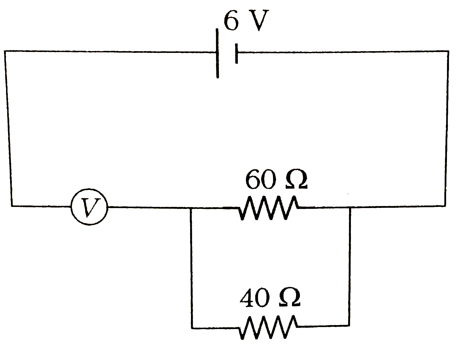
In the circuit shown in the figure, the voltmeter reading is
 A2.4VB3.4VC4.0VD6.0V
In the combination shown in the figure, the ideal voltmeter reading will be
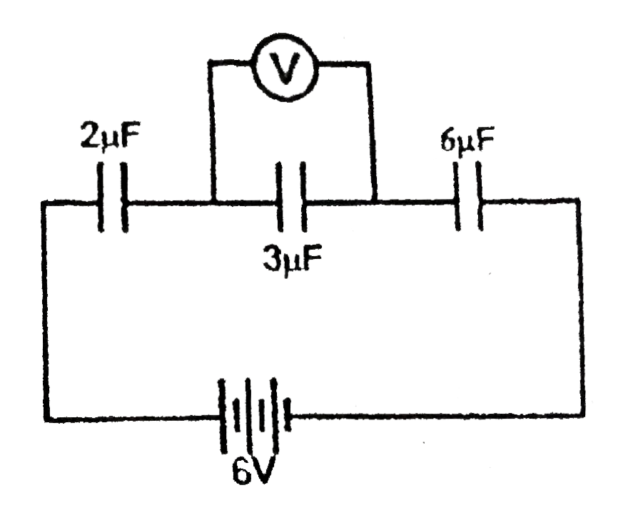 A4.5 VB(1811)VC3VD2V
Iri the circuit shown in figure-3.334, the resistance of voltmeter is6kΩ. The voltmeter reading will be :
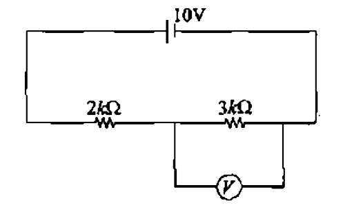 A6VB5VC4VD3V
In the given circuit, the voltmeter reads SV. The resistance of the voltmeter is :
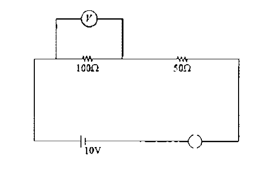
View SolutionIn the given circuit, the voltmeter reads SV. The resistance of the voltmeter is :

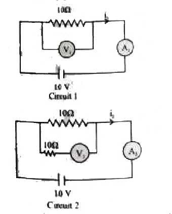
View SolutionIn the circuits shown below, the readings of the voltmeters and the ammeters will be
View SolutionIri the circuit shown in figure-3.334, the resistance of voltmeter is6kΩ. The voltmeter reading will be :

View SolutionIn the circuits shown below, the readings of the voltmeters and the ammeters will be:
View Solution

