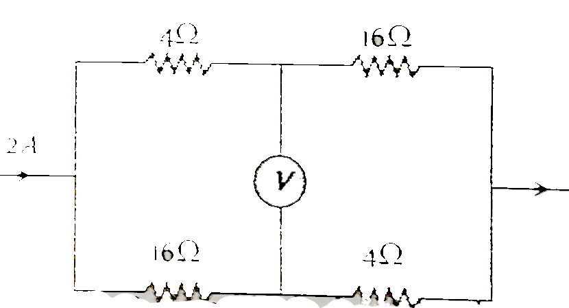
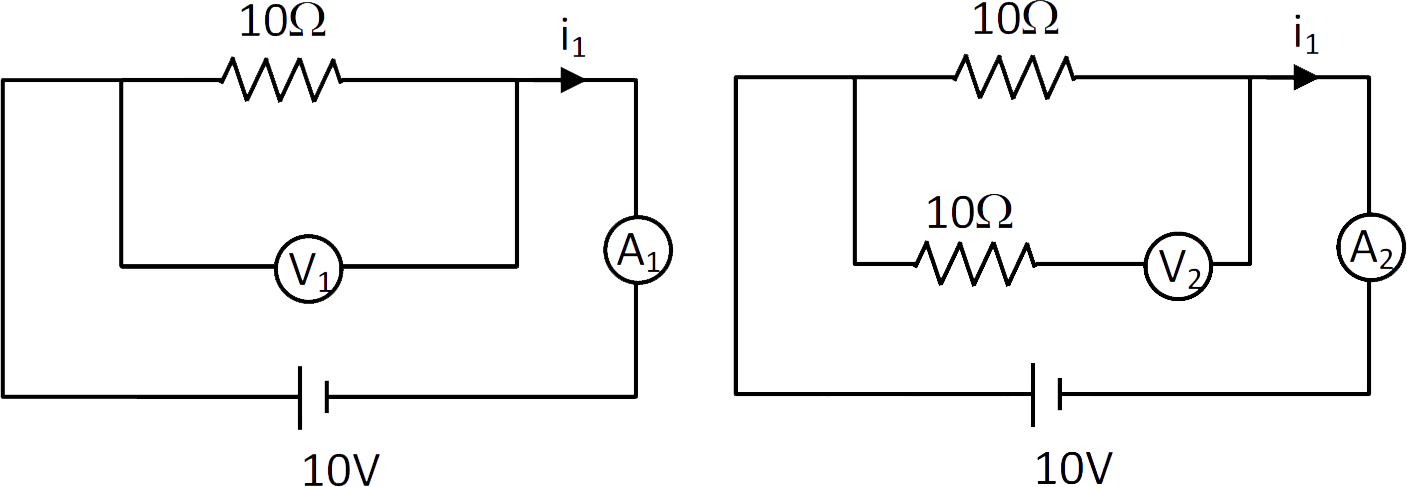
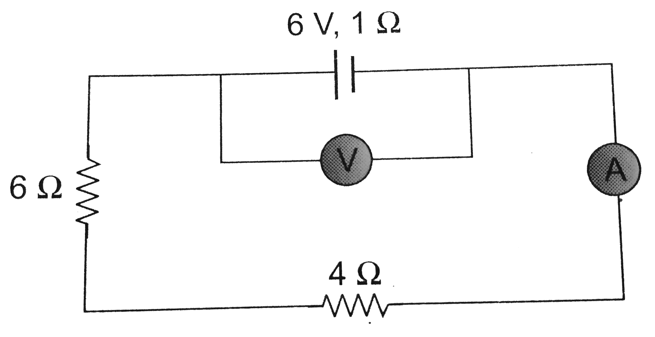
In the circuits shown below, the readings of the voltmeters and the ammeters will be:
A
and
B
and
C
and
D
and
Video Solution
Text Solution
The correct Answer is:D
Resistance for ideal voltemeter
Resistance for ideal ammeter =0
In circuit
|
Topper's Solved these Questions
- NEETBOOK - NEET PREVIOUS YEAR (YEARWISE + CHAPTERWISE)CHAPTER - NEETEXERCISE - QUESTION
95 Videos
- NEETBOOK - NEET PREVIOUS YEAR (YEARWISE + CHAPTERWISE)CHAPTER - NEETEXERCISE - MCQ
95 Videos
- NEETBOOK - NEET PREVIOUS YEAR (YEARWISE + CHAPTERWISE)CHAPTER - NEETEXERCISE - MCQ
95 Videos
- MOTION IN TWO AND THREE DIMENSIONBOOK - NEET PREVIOUS YEAR (YEARWISE + CHAPTERWISE)CHAPTER - MOTION IN TWO AND THREE DIMENSIONEXERCISE - All Questions
47 Videos
- NEET 2020BOOK - NEET PREVIOUS YEAR (YEARWISE + CHAPTERWISE)CHAPTER - NEET 2020EXERCISE - All Questions
45 Videos
Similar Questions
Knowledge Check
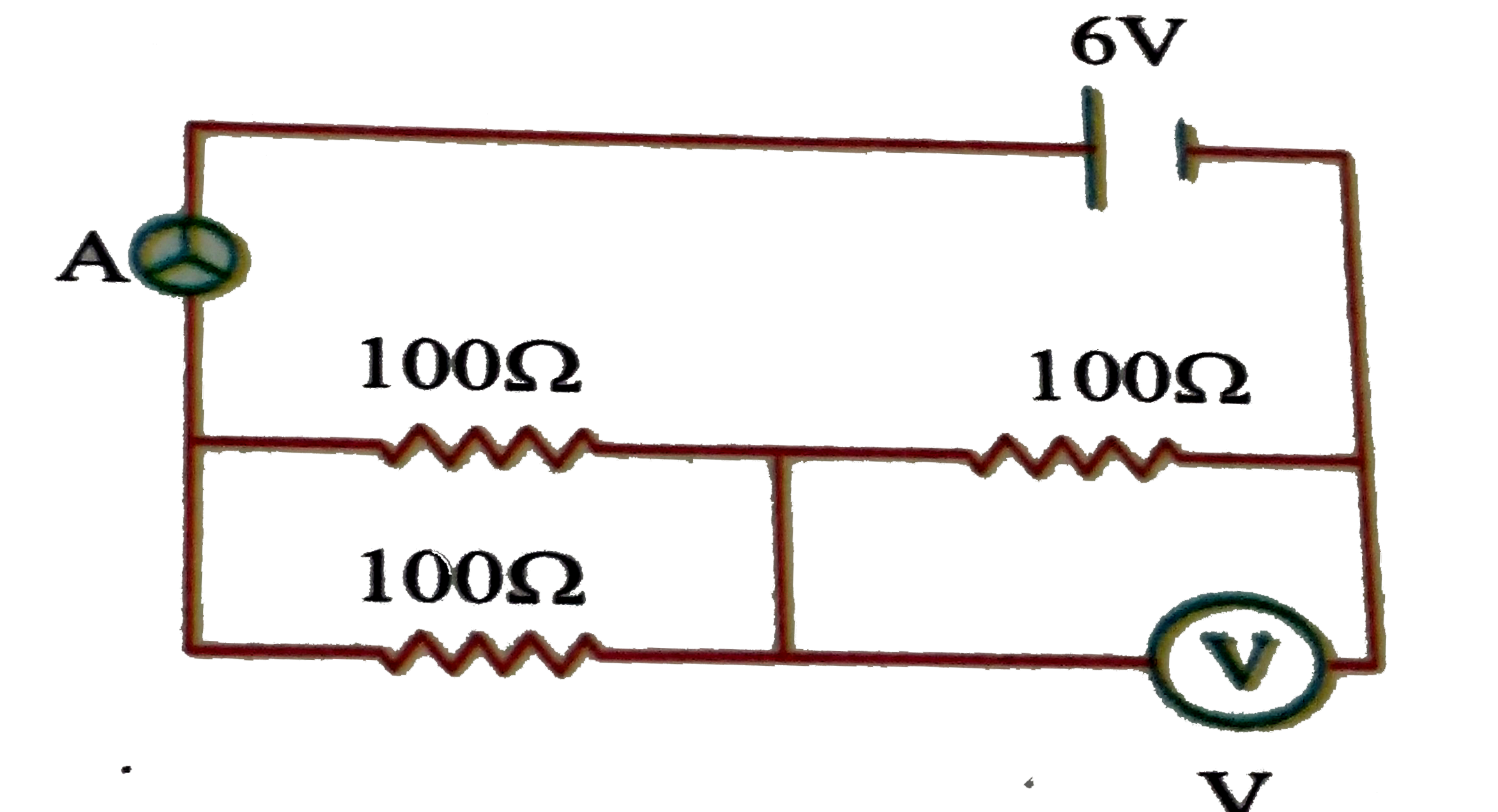
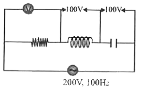
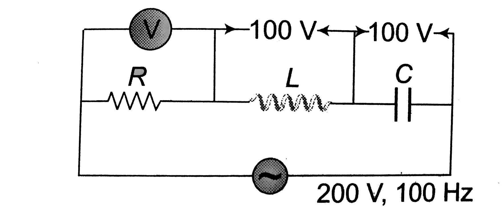
In the circuit shown, the reading of the voltmeter and the ammeter areA4V.0.2AB2V,0.4AC3V,0.6AD4V,0.04AIn the circuit shown below, what will be the reading of the voltmeter and ammeter?
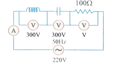
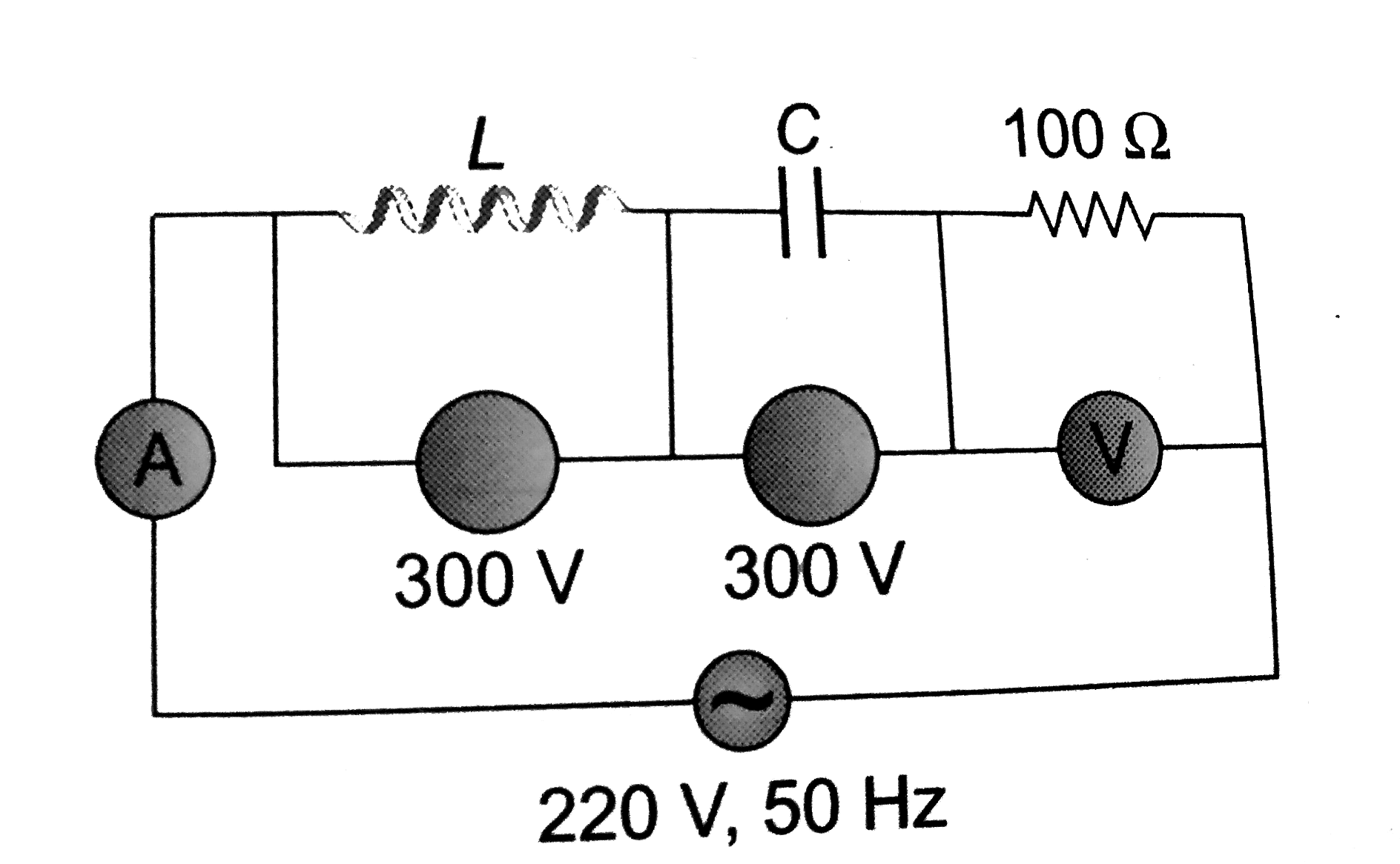 A800V,2AB300V,2AC220V,2.2AD100V,2A
In the circuit shown here, the readings of the ammeter and voltmeter are
 A6A,60VB0.6A,6VC6/11A,60/11VD11/6A,11/60V
In the circuit shown below what will be the reading of the voltmeters and ammeter?
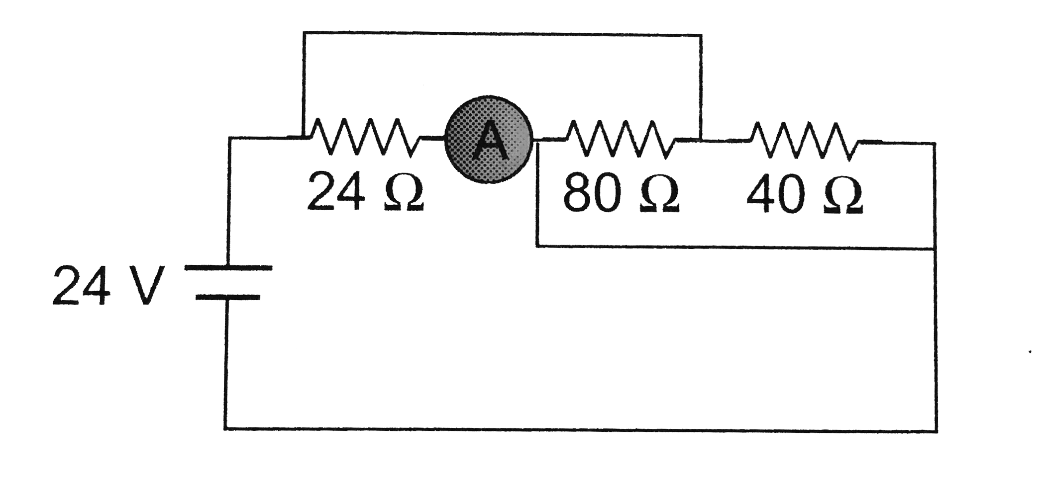
View SolutionIn the circuit shown, the reading of ammeter is:
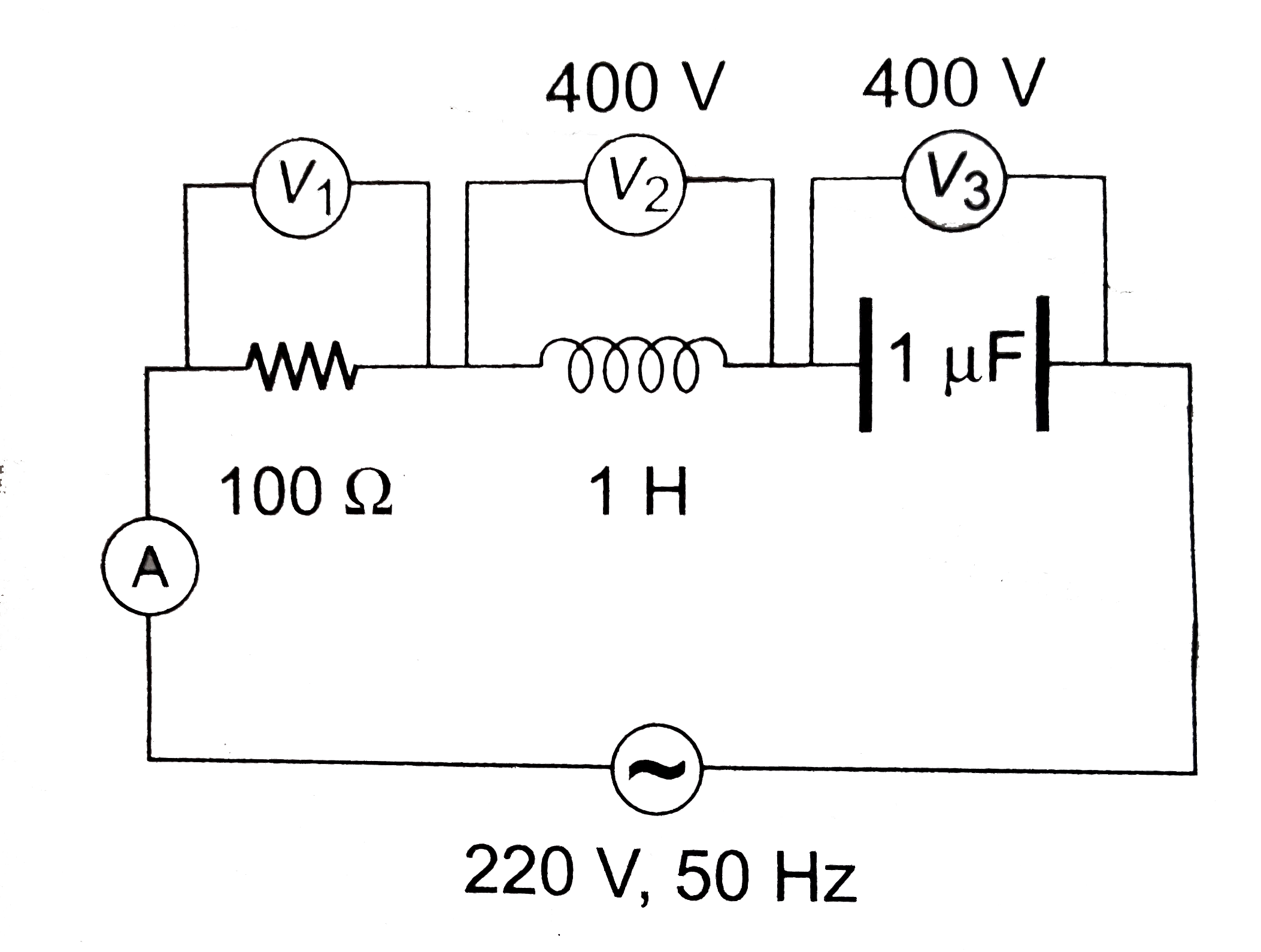
View SolutionIn the given circuit the readings of the voltmeter V1 and the ammeter A are
 .
.
View SolutionIn the circuit given below, what will be the reading of the voltmeter?
View SolutionIn the circuit given below, what will be the reading of the voltmeter?
View Solution

