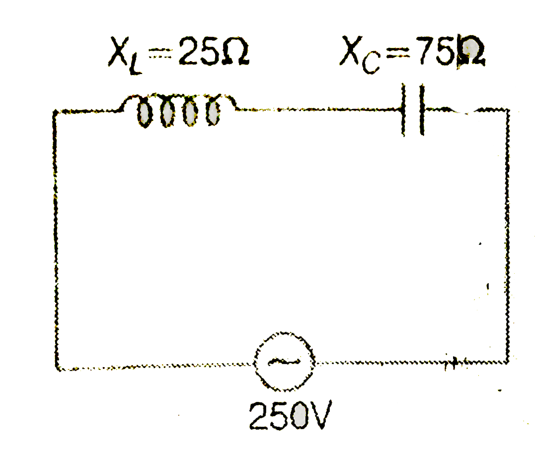
For the circuit shown
A
Current in circuit in 10A
B
Voltage across inductor is 100V
C
Voltage acros capacitor is less than that of supply voltage
D
Voltage across capacitor is more than that of supply voltage
Video Solution
Text Solution
The correct Answer is:D
|
Answer
Step by step video, text & image solution for For the circuit shown by Physics experts to help you in doubts & scoring excellent marks in Class 12 exams.
Updated on:21/07/2023
Related Playlists
Similar Practice Problems
- Question 1 - Select One
Consider the circuit shown in the figure
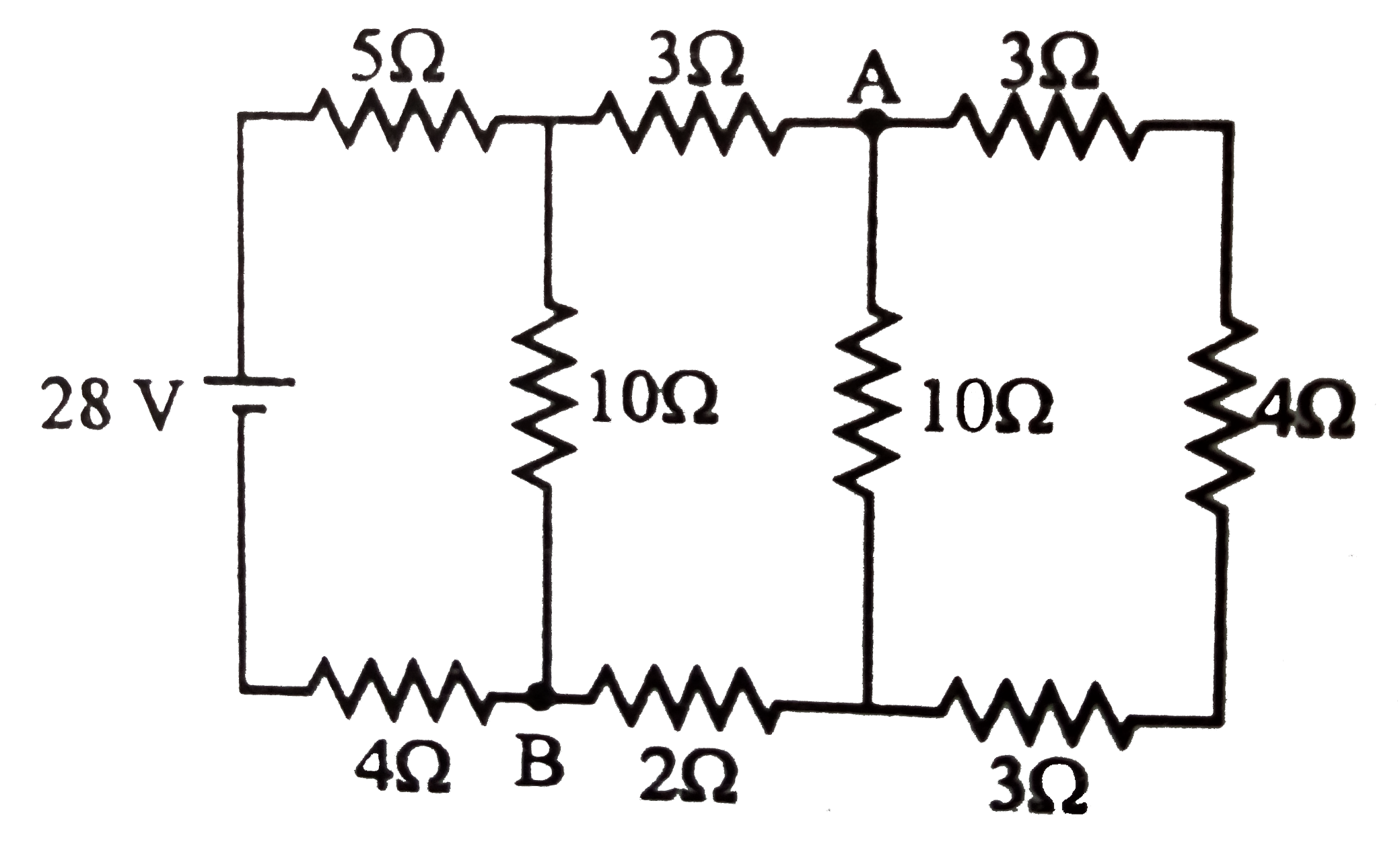 Athe current in the 5Ω resistor is 2ABthe current in the 5Ωresistor is 1ACthe potential difference VA−VB is 10VDthe potential difference VA−VB is 5V
 - Question 1 - Select One or More
Consider the circuit shown in the following figure.
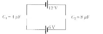 AThe charge on C2 is greater than on C1BThe charge on C1andC2 are the sameCThe potential drops across C1andC2 are the sameDThe potential drops across C1 is greater than that across C2
 - Question 1 - Select One
In the circuit shown
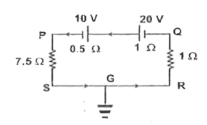 Athe potential at Πs−7.5VBthe potential at Qis−1VCthe potential at R is zeroDthe potential al S is zero
 - Question 1 - Select One
In the circuit shown in the circuit through
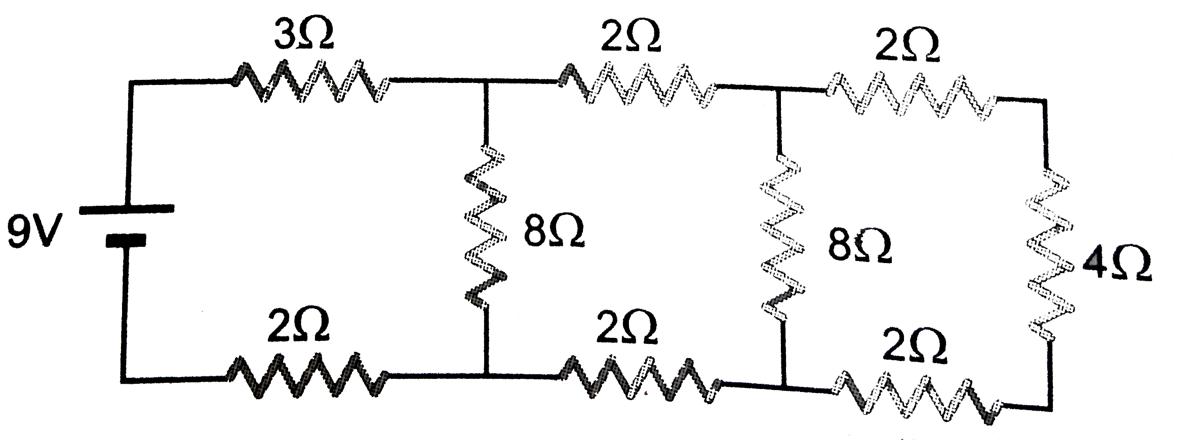 Athe 3Ω resistor is 0.50ABthe 3Ω resistor is 0.25ACthe 4Ω resistor is 0.50ADthe 4Ω resistor is 0.25A
 - Question 1 - Select One
In the circuit shown in figure current in the circuit is
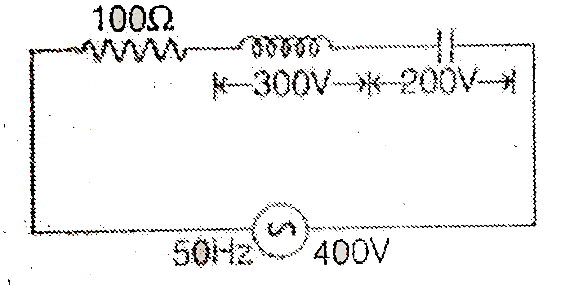 A1.27AB2.23AC4.26AD4 A
 - Question 1 - Select One
Output of the circuit shown below will be
 Azero all the timesBlike half wave rectifier with positive cycles in outputClike half wave rectifier with nagative cycles in outputDlike that of a full wave rectifler
 - Question 1 - Select One or More
In the circuit shown in figure
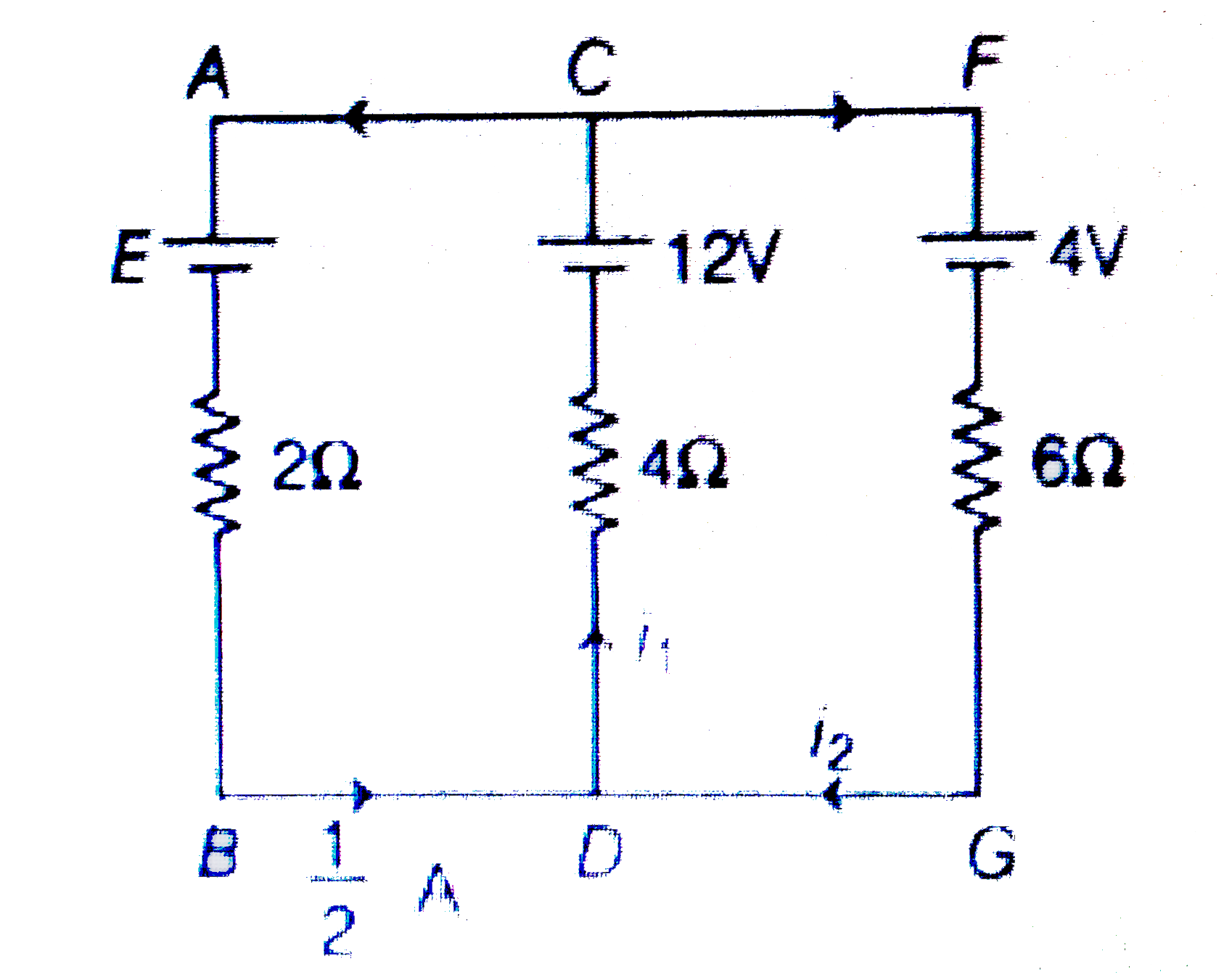 AE = 6.6 VBi1=1.1ACi2=0.5ADE = 4.4 V
 - Question 1 - Select One or More
In the circuit shown in figure
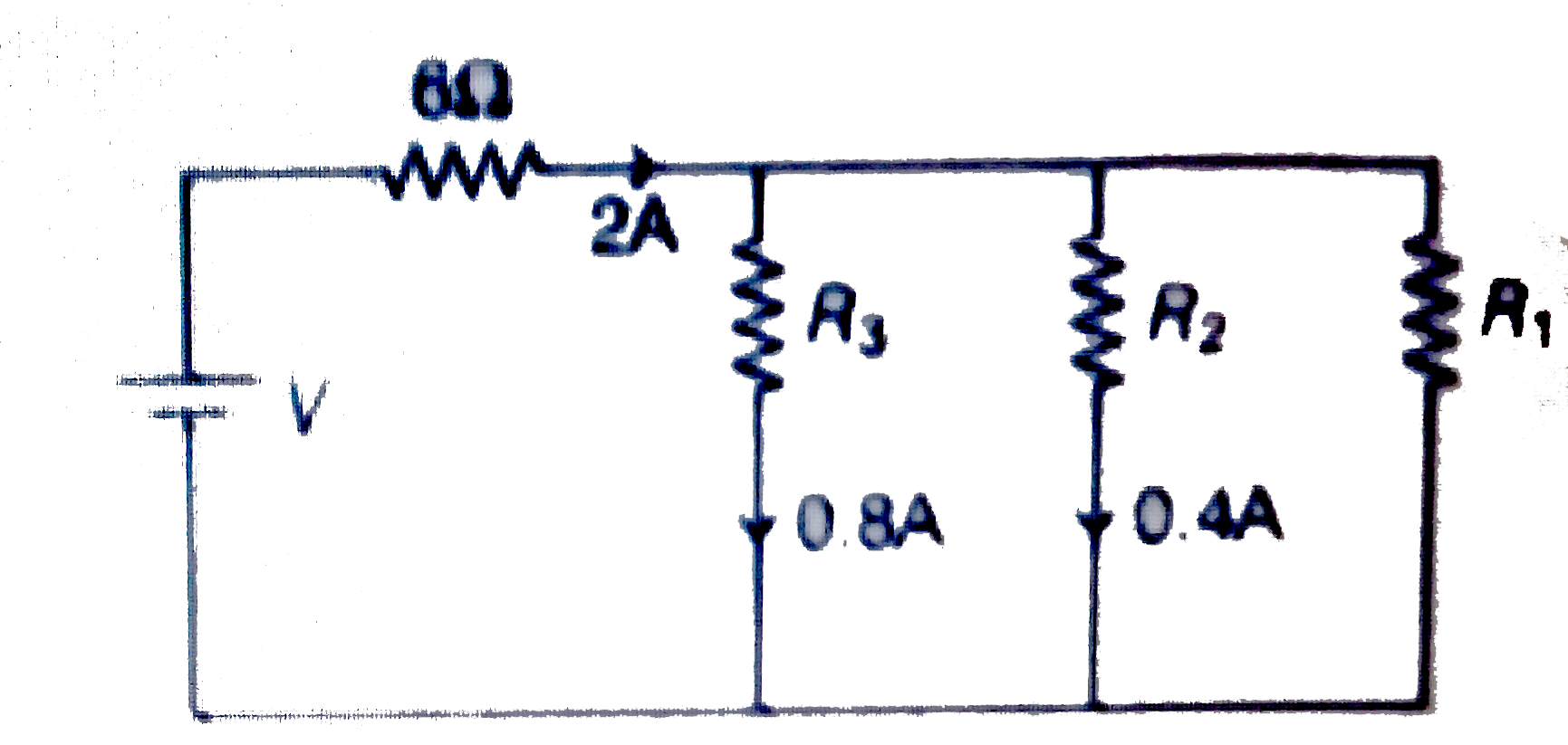 AV = 10 VBR1=10ΩCR2=20ΩDnet resistance of the circuit is 10Ω


