In the circuit diagram shown in Figure E=18V , L=2H, R1=3Ω,R2=6Ω. Switch S is closed at t=0 Match the following:
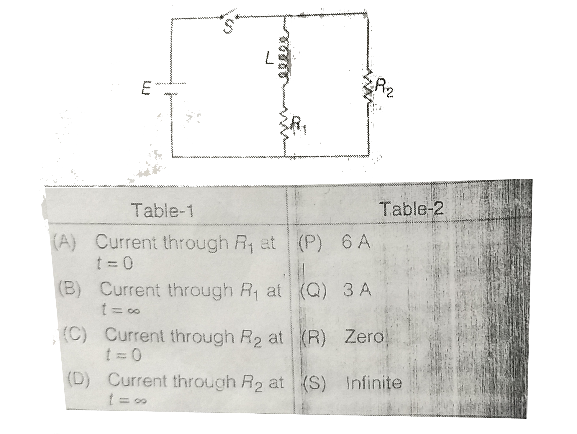
The correct Answer is:(A) R, (B) P, (C) Q, (D) Q
Step by step video, text & image solution for In the circuit diagram shown in Figure E=18V , L=2H, R_(1)=3Omega , R_(2)=6Omega. Switch S is closed at t=0 Match the following: by Physics experts to help you in doubts & scoring excellent marks in Class 12 exams.
Similar Questions
In the circuit shown in figure, E=120V,R1=30.0Ω,R2=50.0Ω and L=0.200H. Switch S is closed at t=0. Just after the switch is closed.
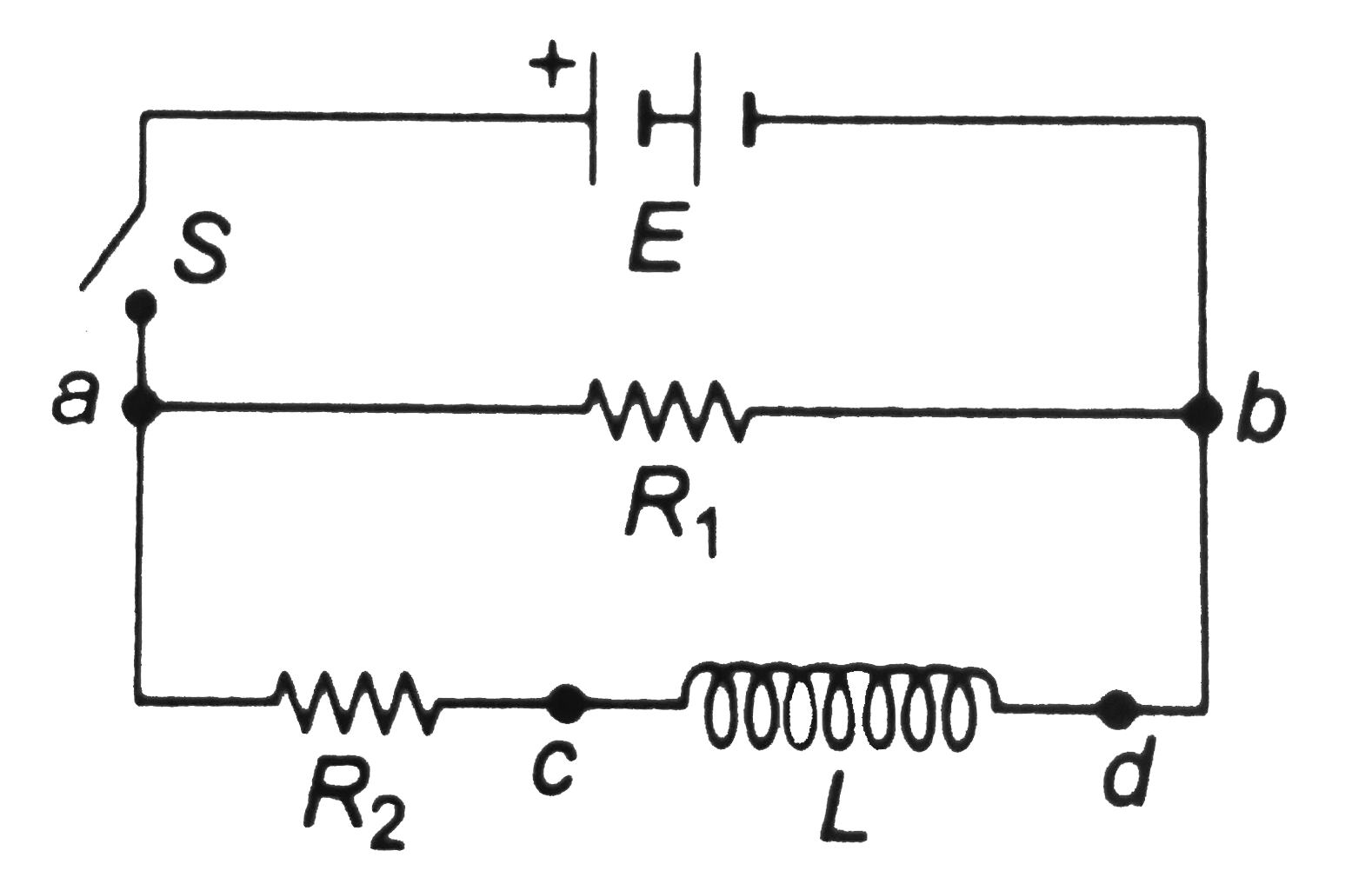
(a) What is the potential difference Vab across the inductor R1?
(b) Which point, a or b, is at higher potential?
(c) What is the potential difference Vcd across the inductor L?
(d) Which point, c or d, is at a higher potential? The switch is left closed for a long time and then is opened. Just after the switch is opened
(e) What is the potential difference Vab across the resistor R1?
(f) Which point a or b, is at a higher potential?
(g) What is the potential difference Vcd across the inductor L?
(h) Which point, c or d, is at a higher potential?View SolutionIn the circuit shown in figure, E = 10 V, r = 1Ω,
R = 4Ω and L = 5H. The circuit is closed at time t = 0.
Then, match the following two columns.
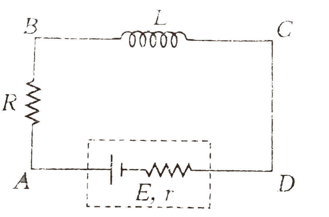
Column IColumn IIA.VAD at t = 0p4VB.VBC at t = 0q8VC.VAB at t =∞r.0VD.VAD at t=∞s.10VView Solution
Knowledge Check
- Question 1 - Select One
In the circuit shown in figure L=10H,R=5Ω,E=15V. The switch S is closed at t=0. At t=2s the current in the circuit is
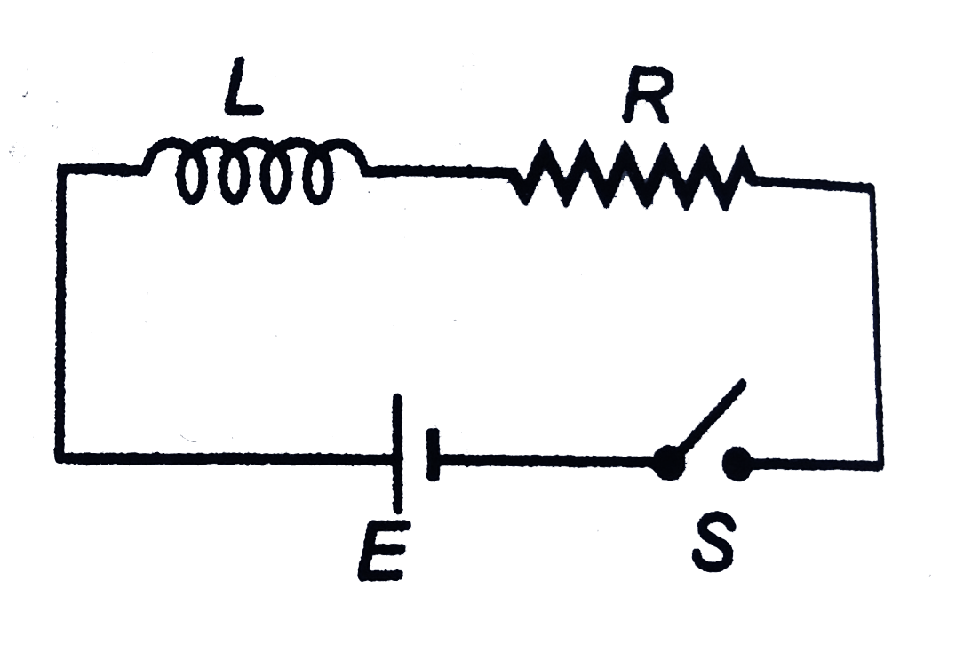 A3(1−1e)AB3(1−1e2)AC3(1e)AD3(1e2)A
 - Question 2 - Select One
In the circuit shows in Fig E=15V, R1=1Ω, R2=1Ω, R3=2Ω, and L=1.5H. The currents flowing through R1,R2,and R3 are i1,i2, and i3, respectively.
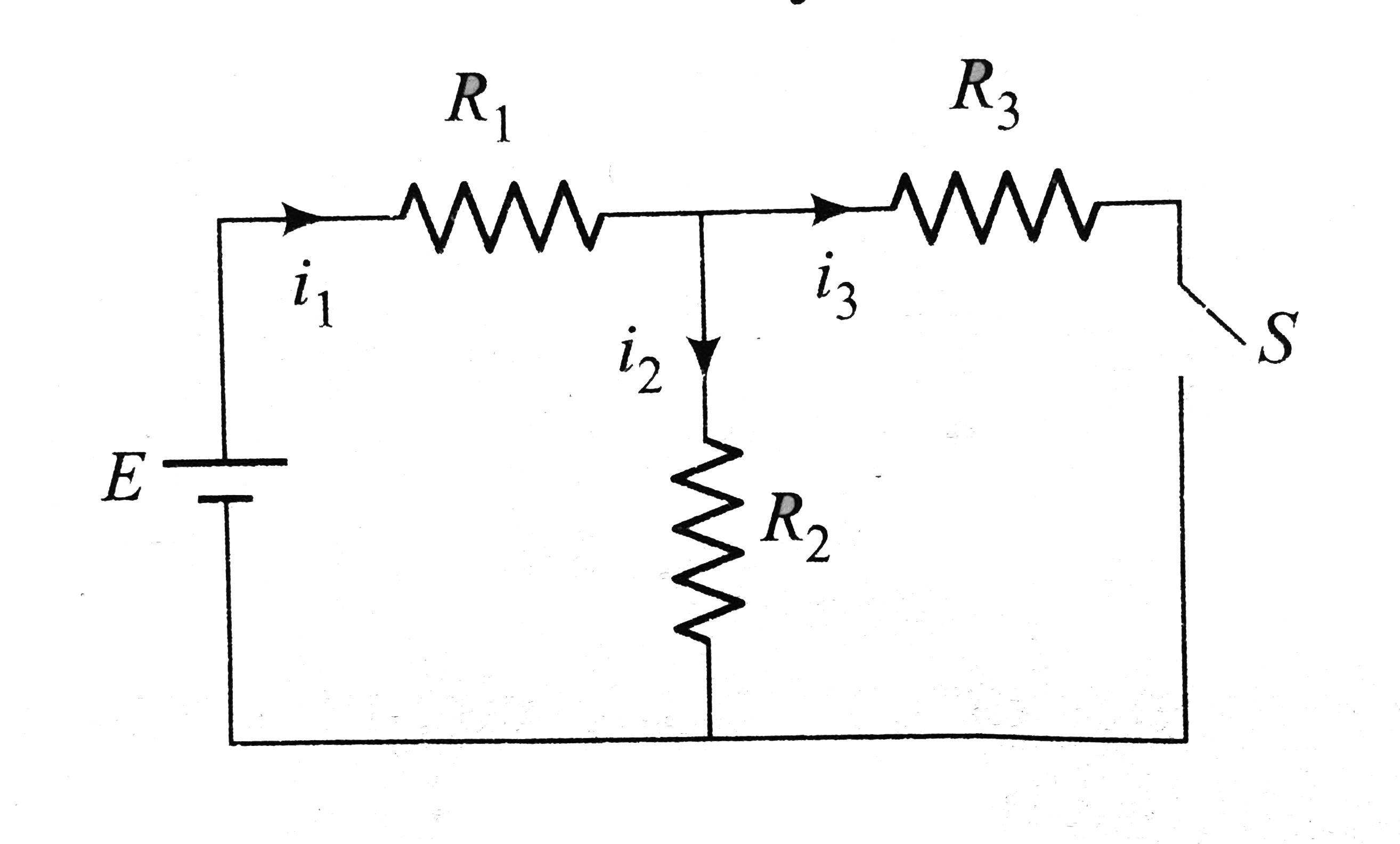
Immediately after tuning switch S on,Ai1=i2=7.5A, i3=0ABi1=i3=5A, i2=0ACi1=i2=9A, i3=0ADi1=i2=i3=0A - Question 3 - Select One
In the circuit shows in Fig E=15V, R1=1Ω, R2=1Ω, R3=2Ω, and L=1.5H. The currents flowing through R1,R2,and R3 are i1,i2, and i3, respectively.
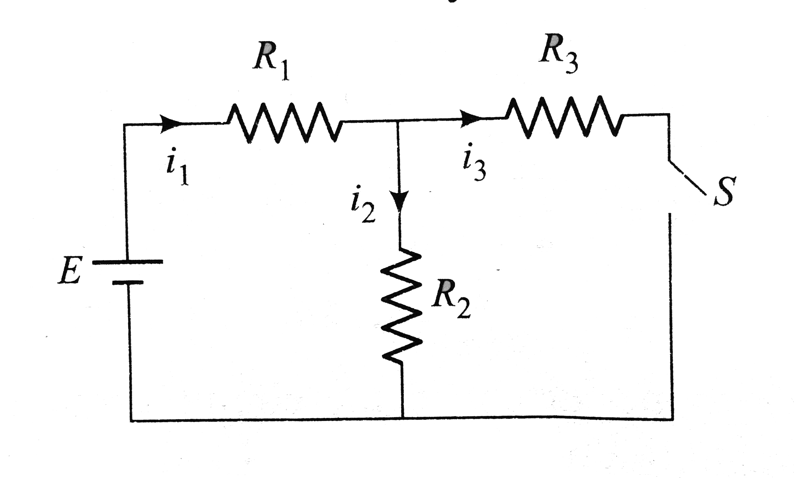
Immediately after connecting switch S,Ai3=0A and di3dt=0As−1Bi3=0A and di3dt≠0As−1Ci3=0A and the rate at which magnetic energy stored is not zeroDNone of these
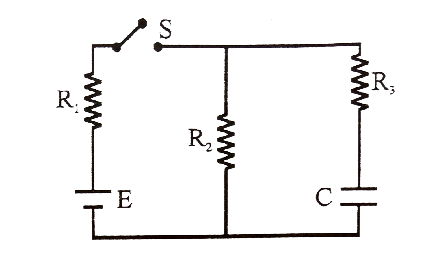
In the circuit shown in figure R1=R1=6R3=300MΩ,C=0.01μF and E−10V. The switch is closed at t=0, find
(a) Charge on capacitor as a function of time
(b) enegry of the capacitor at t=20s
 View Solution
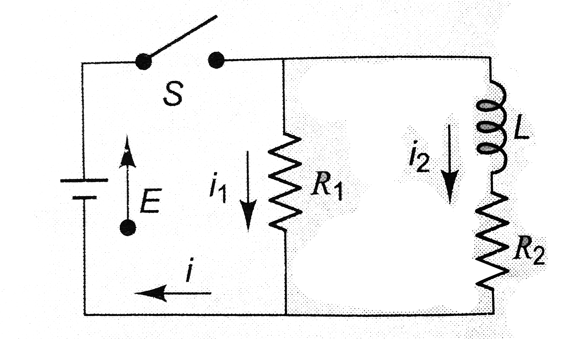
In the circuit shows in Fig. , E=10V, R1=5Ω, R2=10Ω, and L=5H. For the two separate conditions, (i) switch S is just closed and (ii) switch S is closed for a long time, calculate
a. current i1 through R1,
b. current i2 through R2,
c. current i through the switchs,
d. the potential difference across R2,
e. the potential difference across L,
f. di2/dt.
 View Solution
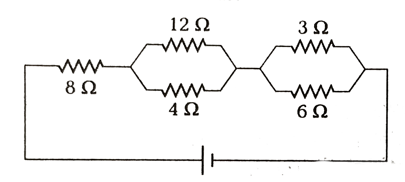
In the circuit diagram shown in figure, potential difference across 3Ω resistance is 20 V. Then, match the following two columns.
 View Solution
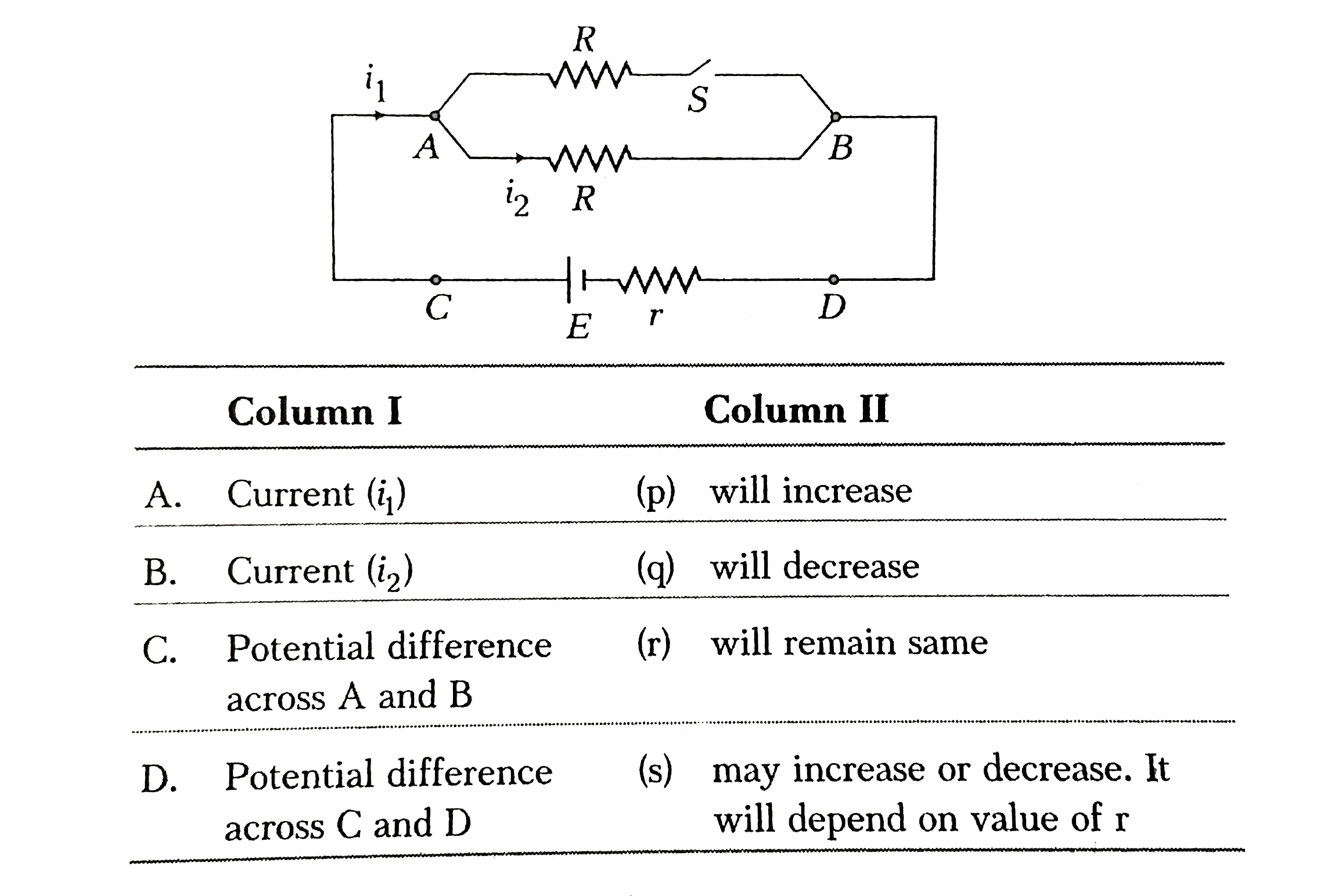
In the circuit diagram shown in figure match the following two columns when switch S is closed.
 View Solution
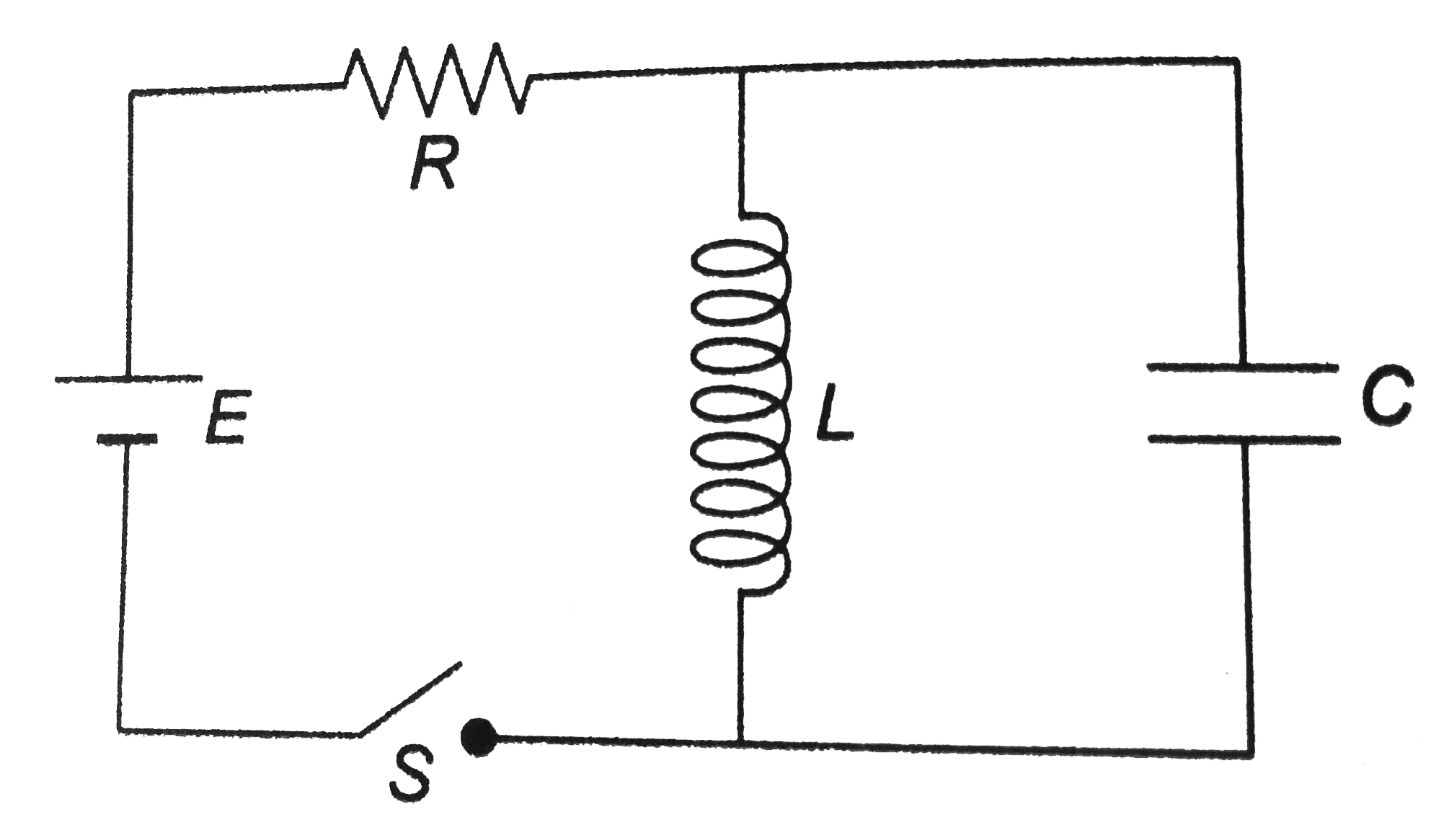
In the circuit shown in the figure, E=50.0V,R=250Ω and C=0.500μF. The switch S is closed for a long time, and no voltage is measured across the capacitor. After the switch is opened, the voltage across the capacitor reaches a maximum value of 150V. What is the inductance L?
 View Solution

