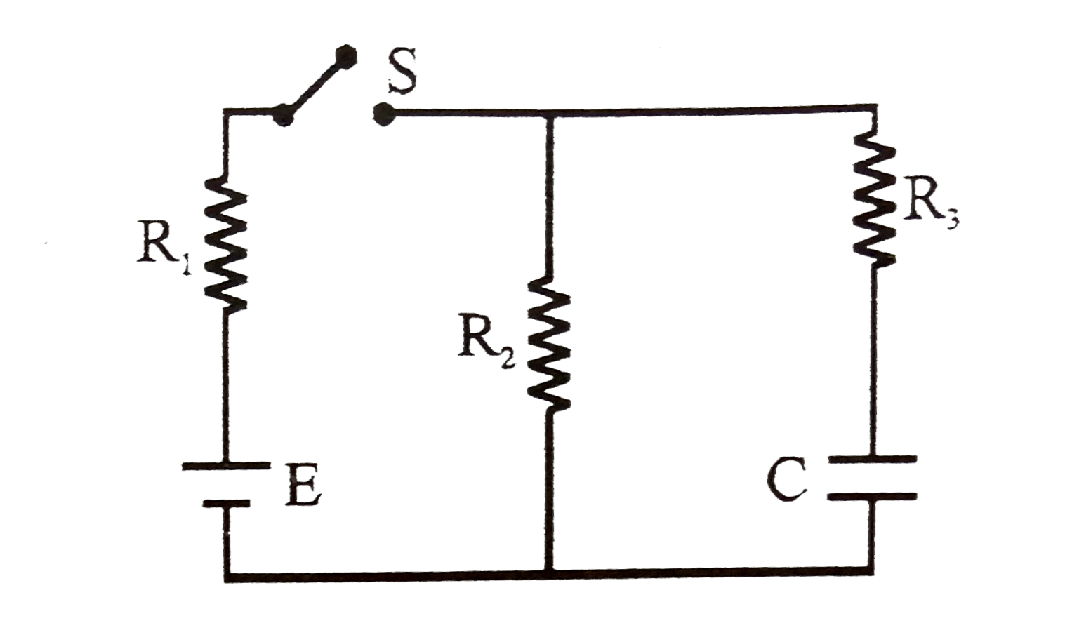
In the circuit shown in figure, E=120V,R1=30.0Ω,R2=50.0Ω and L=0.200H. Switch S is closed at t=0. Just after the switch is closed.
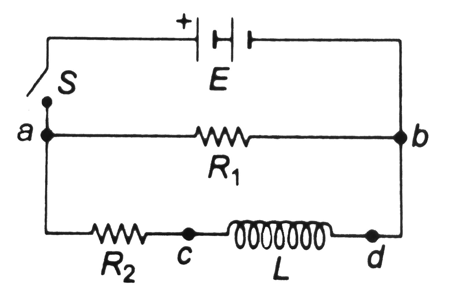
(a) What is the potential difference Vab across the inductor R1?
(b) Which point, a or b, is at higher potential?
(c) What is the potential difference Vcd across the inductor L?
(d) Which point, c or d, is at a higher potential? The switch is left closed for a long time and then is opened. Just after the switch is opened
(e) What is the potential difference Vab across the resistor R1?
(f) Which point a or b, is at a higher potential?
(g) What is the potential difference Vcd across the inductor L?
(h) Which point, c or d, is at a higher potential?
The correct Answer is:D
These are two independent parallel circuits across the battery.
a. Vab=E=120 volt (at all instants)
b.a is higher potential.
c. Vcd will decrease exponentially from 120V to zero.
∴Vcd=120volt, just after the switch is closed.
d. c will be at higher potential.
e. When switch is opeed, current through R1 will immediately become zero. While through R2, will decrease to zero from the value
ER2=2.4A=i0 (say), exponentially. Path of this decay of current will be cdbac.
∴ Just after the switch is opened.
Vab=−i0R1=−2.4×30=−72vo<
f. Point b is at higher potential.
g. Vcd=−i0(R1+R2)=−2.4(80)=−192volt
h. This time point d will be at higher potential.
Topper's Solved these Questions
- ELECTROMAGNETIC INDUCTIONBOOK - DC PANDEYCHAPTER - ELECTROMAGNETIC INDUCTIONEXERCISE - Check point
60 Videos
- ELECTROMAGNETIC INDUCTIONBOOK - DC PANDEYCHAPTER - ELECTROMAGNETIC INDUCTIONEXERCISE - Taking it together
119 Videos
- ELECTROMAGNETIC INDUCTIONBOOK - DC PANDEYCHAPTER - ELECTROMAGNETIC INDUCTIONEXERCISE - SUBJECTIVE TYPE
1 Videos
- CURRENT ELECTRICITYBOOK - DC PANDEYCHAPTER - CURRENT ELECTRICITYEXERCISE - Medical entrances gallery
97 Videos
- ELECTROMAGNETIC WAVESBOOK - DC PANDEYCHAPTER - ELECTROMAGNETIC WAVESEXERCISE - Sec C
22 Videos
Similar Questions
Knowledge Check
In the circuit shown in figure L=10H,R=5Ω,E=15V. The switch S is closed at t=0. At t=2s the current in the circuit is
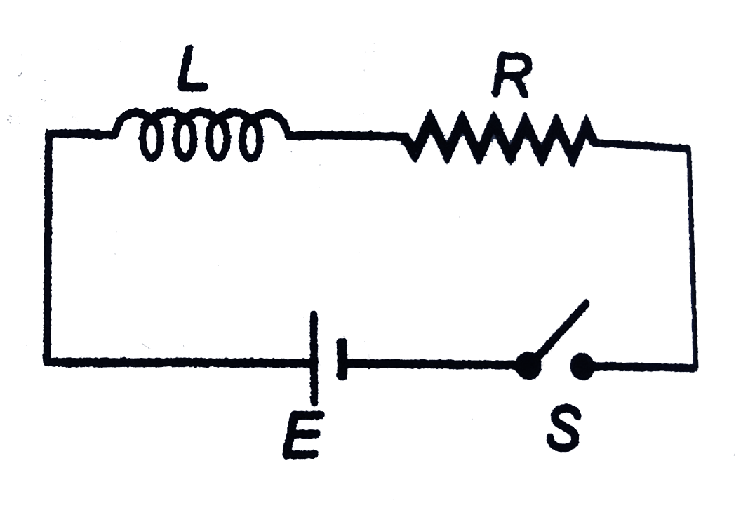 A3(1−1e)AB3(1−1e2)AC3(1e)AD3(1e2)A
In the circuit shown in fig, switch S was closed for long time. At time t-0, teh switch is opened again. The maximum potential difference across teh plates of the capacitor after the switch is opened is
 A10VB100VC20VD200V
In the inductive circuit given in the figure, the current rises after the switch is closed. At instant when the current is 15 mA, then potential difference across the inductor will be-
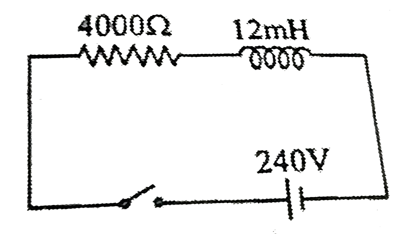 AzeroB240 VC180 VD60 V
In the circuit shown in figure

E1=10V,E2=4V,r1=r2=1Ω and R=2Ω.
Find the potential difference across battery 1 and battery 2.
View SolutionA capacitor with an initial potential difference of 80.0 V is discharged through a resistor when a switch between them is closed at t=0. At t= 10.0s, the potential difference across the capacitor is 1.00V (a) What is time constant of the circuit? (b) What is the potential difference across the capacilor
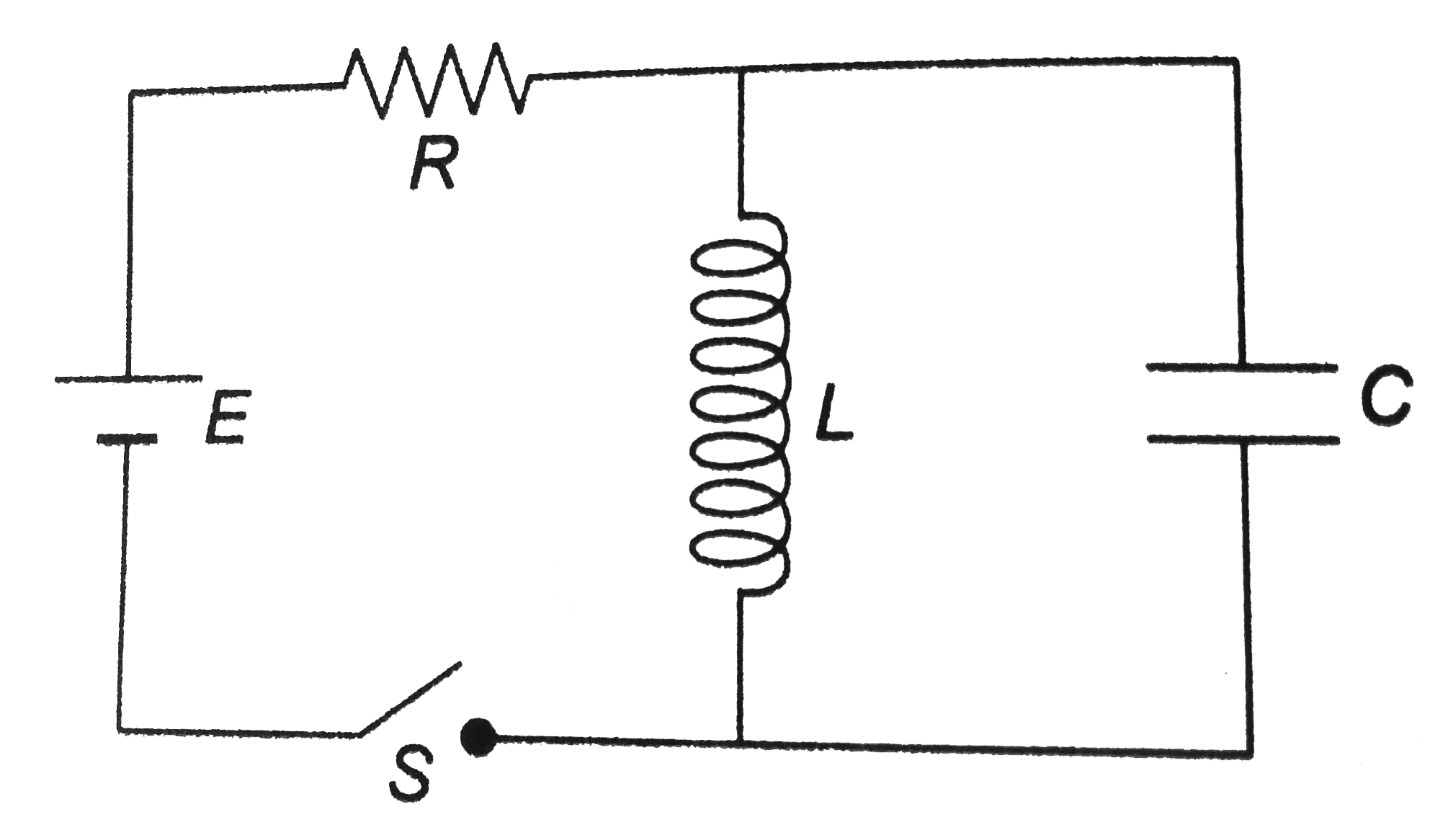
View SolutionIn the circuit shown in the figure, E=50.0V,R=250Ω and C=0.500μF. The switch S is closed for a long time, and no voltage is measured across the capacitor. After the switch is opened, the voltage across the capacitor reaches a maximum value of 150V. What is the inductance L?
View SolutionIn the circuit shown in figure R1=R1=6R3=300MΩ,C=0.01μF and E−10V. The switch is closed at t=0, find
(a) Charge on capacitor as a function of time
(b) enegry of the capacitor at t=20s
View SolutionIn the circuit shown in figure switch S is closed at time t=0
Potential difference across 3Ω resistance at time t is given by
View Solution

_PHY_E06_157_Q01.png)