A constant voltage of 25 V is applied to a series L-R circuit at t = 0 , by closing a switch . What is the pitential difference across the resister and the inductor at time t = 0? Solution in Telugu
0 V, 25 V
12.5V, 1.25 V
10 V, 15 V
25 V, 0 V
The correct Answer is:B
From the closed loop (1) , 12−500i1−i1R=0
Rightarrow 12=150(R+500)
From the closed loop (2),2−i1(500)−2=0
i1=150
Substitute equation (1) , wewe get ,
12=150(R+500)⇒600=R+500
R=100ω

Topper's Solved these Questions
Similar Questions
A carrier wave of peak voltage 12 volts is used to transmit a signal. If the modulation index is 75%, the peak voltage of the modulating signal is
View SolutionThe ratio of energies of emtiied radiation by a black body at 600 K and 900 K when the surrounding temperature is 300, is
View SolutionA constant voltage is applied to a series R-L circuit by closing the switch. The voltage across inductor (L=2H) is 20V at t=0 and drops of 5V and 20 ms . The value of R in Omega is
View SolutionA 1 -k Omega resistor is connected in series with a 10-mH inductor, a 30 V battery and an open switch. At time t= 0 , the switch is suddenly closed. a. What is the maximum current in this circuit and when does it occur? b. What are the voltage drops across the inductor and across the resistor 20 mu s after the switch is closed? c. On a single set of axes, sketch the voltage across the resistor and the voltage across the inductor as functions of time. Also, sketch a graph of the current in the circuit as s function of time.
View SolutionA circuit consists of a capacitor with capacitance C and a coil of inductance L connected in series, as well as a switch and a resistance equal to the critical value for this circuit. With the switch disconnected, the capacitor was charged to a voltage V0, and at the moment t=0, the switch was closed . Find the corrent I in the circuit as a function of time t.What is Imax equal to ?
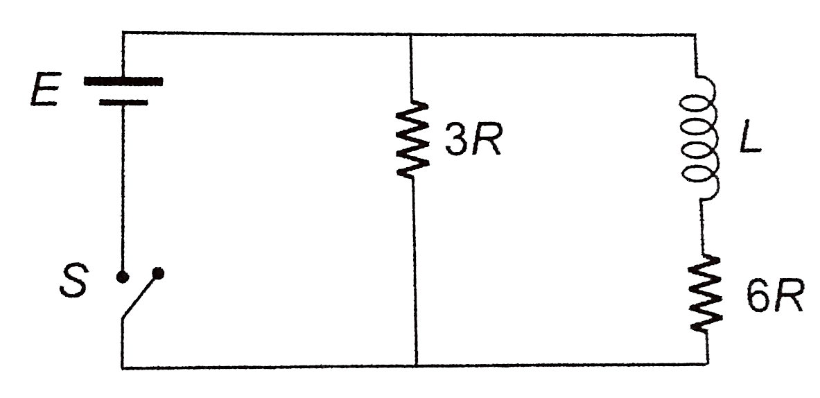
View SolutionAt t=0 , switch S is closed. Find time constant of the circuit and current through inductor as a function of time t .


View SolutionIn the circuit shown, the switch is closed at time t = 0. Which of the graphs shown below best represents the voltage across the inductor, as seen on an oscilloscope ?
View SolutionIn the circuit shown in figure switch S is closed at time t=0

Potential difference across 3Ω resistance at time t is given by
View SolutionA voltage V0sinωt is applied across a series combination of resistance R and inductor L. The peak value of the current in the circuit is
View SolutionThe figure below shows a battery of emf epsilon connected to an inductor L and resistance R in series. If the switch is closed at t=0, then the total charge that flows from the battery in time constant of the circuit is
View SolutionAs shown in the figure, a battery of emf is connected to an inductor L and resistance R in series. The switch is closed at . The total charge that flows from the battery, between t=t_e and t=2t_e ( t_e is the time constant of the circuit) is:
View SolutionA sinusoidal voltage Vsin(at) is applied across a series combination of resistance R and inductor L. The amplitude of the current in the circuit is
View SolutionIn an A.C. series circuit of L-R voltage applied is 220 V, if the potential difference across two ends on inductor is 176 V then the potential difference across two ends of the resistance will be ……
View SolutionA constant voltage is applied to a series R-L circuit by closing the switch. The voltage across inductor (L=2H) is 20V at t=0 and drops of 5V and 20 ms . The value of R in Omega is
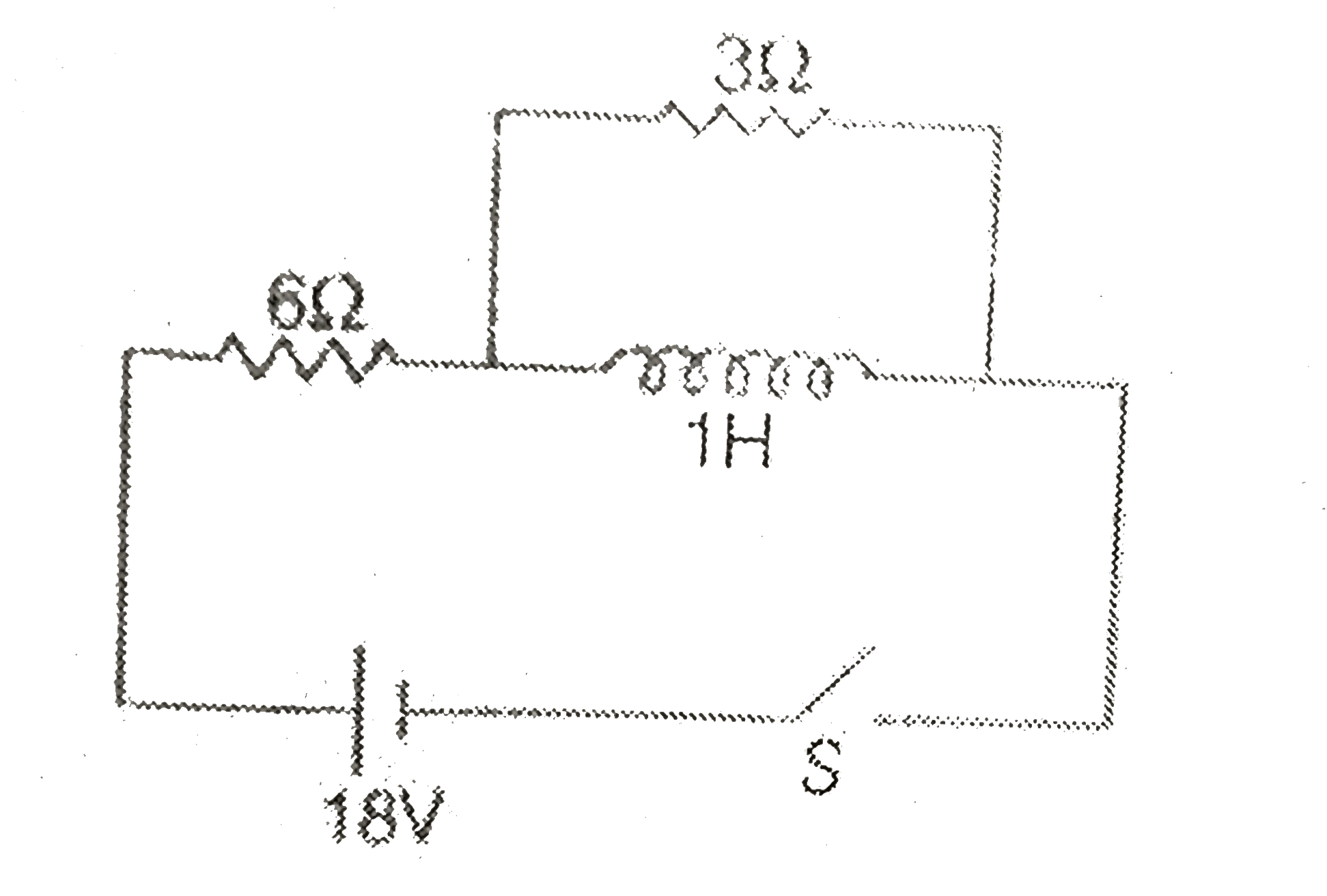
View SolutionIn the circuit shown, switch S is closed at time t = 0 . Find the current through the inductor as a function of time t .
View SolutionIn the circuit shown in figure switch S is closed at time t=0

Potential difference across 3Ω resistance at time t is given by
View Solution
