A current of 2 A flows in an electric circuit as shown in figure . The potential difference (VR and V3 are potenstials at R and S respectively )is

A
-4
B
(+)2
C
(+)4
D
(-)2
Text Solution
The correct Answer is:C
Inductive reacgance , XL=ωL
= 70×103×100×106
= 7Ω
Capacitive reactance , xc=1ωc
=170×103×1×10−6
= 1007
Here , XC>XL
Therefore this circuit effctively behaves as series R-Circuit.

|
Topper's Solved these Questions
Similar Questions
Knowledge Check
A current of 2 A flows in an electric circuit as shown in figure. The potential difference (VR−VS), in volts (VR and VS are potentials at R and S respectively is
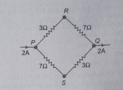 A-4B(+2)C(+4)D-2
A current of 2 A flows in an electric circuit as shown in figure. The potential difference (VR−VS), in volts (VR and VS are potentials at R and S respectively is
 A-4B(+2)C(+4)D-2
A current of 2 A flows in an electric circuit as shown in figure. The potential difference (VR−VS), in volts (VE and VS are potenitals at R and S respectively) is
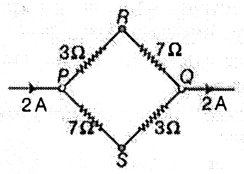 A−4B+2C+4D−2
A current of 2A flows in a system of conductor as shown. The potential difference (VA−VB)
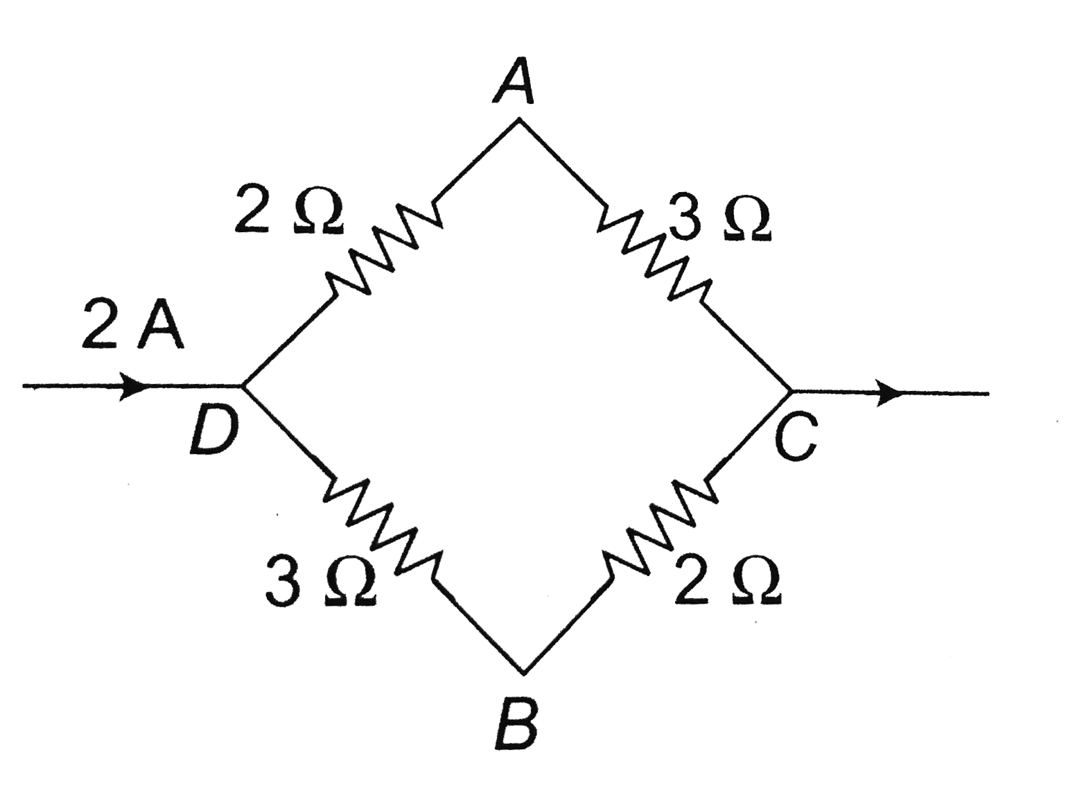
View SolutionIn the circuit shown in figure 3.154 find the potential difference VA−VD
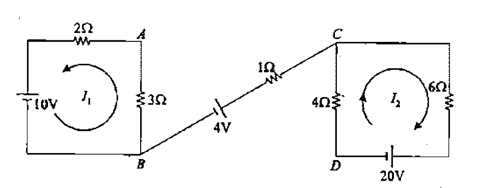
View Solution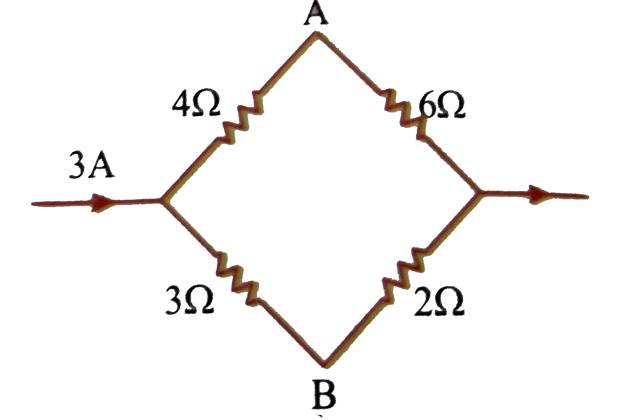
A current of 3A flows in a circuit shown in the figure. The potential difference between A and b is
View SolutionA current of 2A flows in a system of conductor as shown. The potential difference (VA−VB)

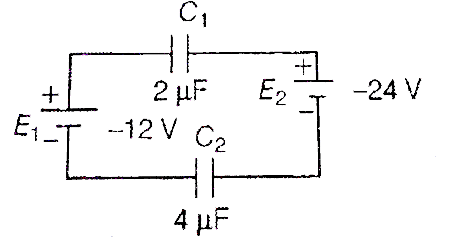
View SolutionTwo capacitors C1 and C2 are connected in a circuit as shown in figure. The potential difference (VA−VB) is
View Solution
